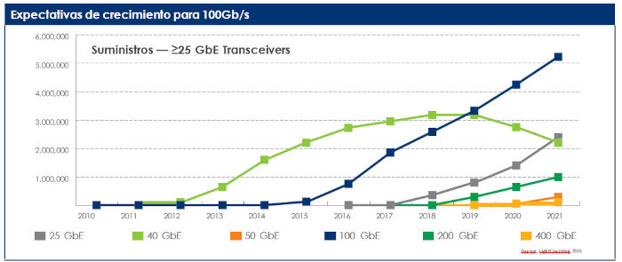
In data centers, demand for 40 Gbps peaked in 2018. Now, there is significant growth for 100 Gbps links and parallel growth for 25 Gbps links. Focusing more on the 100 Gbps segment, 100GBASE-SR4 and 2 km range transceivers account for the majority of 100 Gbps demand.
The growth of both 25 Gbps and 100 Gbps links is largely due to the new IEEE (Institute of Electrical and Electronics Engineers) and MSA (Multisource Agreement) specifications for 25 Gbps links (IEEE 802.3bm, PSM4, and CWDM4). Previously, the preferred solution for 100 Gbps was 10 Gbps over 10 lanes (100GBASE-SR10), following the earlier IEEE 802.3ba specifications. But the adoption of 25 Gbps per lane in IEEE 802.3bm has spurred the growth of new 100 Gbps solutions now on the market. Currently, there are quite a few 100 Gbps transceivers using MPO connectors.
The adoption rate of faster speeds and new transceiver form factors is accelerating rapidly. With groups looking to develop 50 Gbps and 100 Gbps links for 400 and 800 Gbps transceivers, network administrators must be prepared to work with MPO connectors. Keep your cabling infrastructure flexible, as the adoption of next-generation speeds is closer than you think, and the sheer number of options can make the path forward far from certain.
MPO Connection Standards:
Although data centers are actively migrating to higher speeds, most enterprise data centers currently use primarily 10 Gbps switches and 1 Gbps servers.
Cloud networks have operated at 40 Gbps uplinks and 10 Gbps on the server for the past few years. As noted earlier, these networks will move to 100 Gbps uplinks and 25 Gbps on the server over time. The MPO connector has become the common interface for short-range 40 and 100 Gbps transceivers.
Beyond the previously mentioned 100GBASE-SR4 and SR10, another popular specification option for 100 Gbps is 100GBASE-PSM4. It uses a parallel single-mode fiber infrastructure to support spans of at least 500 meters. It allows compatibility with multiple electrical form factors, including QSFP, CFP, and integrated optical engines.
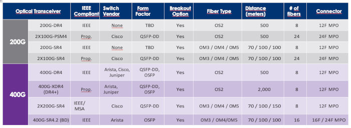
But with the explosion in fiber growth, the cabling community has been scrambling for new standards to address higher data rates. With 200 Gbps transceiver options, only two are currently available: the 2x100-PSM4 single-mode and 2x100-SR4 multi-mode, as highlighted below. These are proprietary options introduced by Cisco, and both are based on 24-fiber MPO connectors.
Among current 400 Gbps transceivers using MPO connections, the 400G-DR4 single-mode and 400G-SR4.2 multi-mode transceivers are likely to become the most common in the coming years. The 400G-DR4 uses four optical channels (eight fibers), each delivering 100 Gbps. The BiDi 400G-SR4.2 solution, originally introduced by an MSA manufacturer, is currently under development by IEEE P802.3cm, with a planned release date in early 2020.
Tables 1 and 2: Transceivers that require MPO connections

Differences between MPO and MTP
MPO or MTP (push-on multifiber termination) terminated cables are widely used in high-density environments. The terms MPO and MTP are often used interchangeably.
However, there is a technical difference. MPO is a type of fiber connector, while MTP is a registered trademark of an MPO connector manufactured by US Conec. All MTP connectors are MPO, but not all MPO connectors are MTP. Visually, there is little difference between the two connectors, and at cabling and transceiver interfaces, they are compatible.
Designing with MPO Connectors: Basic Considerations.
MPO connectors are typically available with 8, 12, or 24 fibers for common data center and LAN applications. Other fiber counts are available, such as 32, 48, 60, or 72 fibers, but these are typically used for special super-high-density multi-fiber arrays in large-scale optical switches.
Unlike single-fiber connectors, which are all male, MPO connectors are either male (with alignment pins) or female (without alignment pins). To mate two MPO connectors using an adapter, one connector must have pins, and the other must be pinless (see Figure 2). The function of the alignment pins is to ensure that the fibers are perfectly aligned with each other, guaranteeing a successful mating.

MPO connectors are often color-coded to help contractors distinguish between different fiber types and adhere to single-mode specifications. MPO connectors are designed for both single-mode and multimode multifiber cables.
In single-mode OS2 applications, as specified by the Telecommunications Industry Association (TIA), the cable jacket is yellow.
The connector color will vary depending on the connector type. Ultra Physical Contact (UPC) connectors are also yellow, while Angled Physical Contact (APC) connectors are green. With multimode OM3/OM4 fibers, both the MPO connectors and the cable jacket will be aqua, according to TIA specifications.
An additional complexity in implementing MPO connectors is understanding the number of fibers in the connectors you are trying to connect. Due to the universal mating capability of some MPO connectors, it is possible to connect a 12-fiber MPO to a 24-fiber MPO. However, doing so will not result in proper mating and can cause confusion during moves, additions, or changes, or when new network installations are connected to a legacy installation. Leviton introduced a color-coded jacket to aid in this task (see Figure 3). On both single-mode and multimode cables, a red jacket indicates a 24-fiber connector, a 12-fiber connector is aquamarine on multimode connectors or black on single-mode connectors, and a gray jacket indicates an 8-fiber connector. Similarly, for adapters, a red MTP adapter or coupler indicates a 24-fiber connector, and a black one indicates a 12-fiber connection.

There are additional levels of complexity to consider for some next-generation transceivers that use MPO connectors. In some transceiver specifications being developed for 400 GB/s, new MPO connector options, such as 16-fiber and 32-fiber connectors, are being introduced. Connector manufacturers are working with design features like key offset to help prevent unintentional mating of the new options with legacy MPO connectors. To fit the four additional fibers between the alignment pins in the ferrule, the pin holes will also be moved closer to the edge of the connector. This means that the new 16- and 32-fiber MPO connectors cannot properly mate with existing 8-, 12-, and 24-fiber connectors.
Basic MPO Connector Cleaning Concepts
: An important consideration when using MPO connectors is that they are notoriously more difficult to keep clean. The connector interface has many more fibers than an LC connector. Keeping 8, 12, or 24 fibers clean on the end face of a single connector can be challenging.
However, it is essential that MPO connectors be kept clean. When clean, the fiber cores can align, and light passes through neatly and easily. But if dirt gets into the ferrule, the dirt particles will break off and migrate across the ferrule end face when a connection is attempted. The dirt creates air gaps, retroreflection, and insertion loss, as shown in Figure 4.
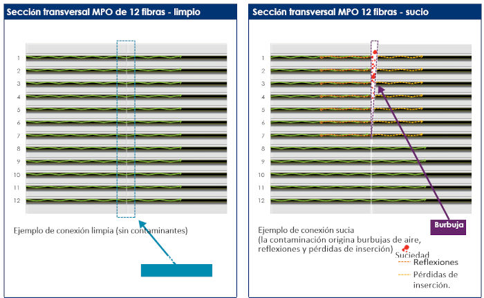
If the MPO connector is connected to a transceiver (switching port), it becomes difficult for the transmitter to connect, and the transceiver's lifespan can be affected.
Fortunately, the solution is simple: inspect before connecting. It's important to have a good visual inspection tool for the MPO connector. Many inspection microscopes are available from optical test equipment suppliers. Fluke, VIAVI, and Exfo are among the most popular.
If the connector is clean after inspection, proceed and connect the MPO. If not, clean and re-inspect. For single-fiber ceramic ferrules, it is recommended that the procedure begin with dry cleaning, and if anything is encrusted, proceed to wet cleaning, then finish with dry cleaning. With MPOs, wet cleaning is more frequently required to properly maintain one side of the ferrule end clean. Because there are several fibers packed closely together, factors such as contaminants and static or humidity, which attract contaminants to the surface, make achieving uniform cleaning more difficult. Wet cleaning should be performed with suitable fiber cleaning solutions, as even high-purity isopropyl alcohol can leave residue from the water that does not evaporate. Applying a small amount of cleaning solution from a lint-free wipe to the end of the one-click MPO cleaning probe is a suitable way to clean the connector end of a pre-connected cassette.
Polarity Considerations in MPO:
Achieving polarity is another challenge with MPO. Polarity defines the direction of the light path or flow, much like the direction of an electric current. In fiber optics, this is called fiber AB-CS polarity. To send data via light signals, the transmit signal on a fiber optic link at one end of the cable must match the corresponding receiver signal at the other end. While this concept may seem simple, it becomes more complex with multi-fiber MPO cables and connectors.
The industry standard TIA-568.3-D names three different polarity methods for MPO: Method A, Method B, and Method C. Each method uses different types of MPO cables.
When examining 12 fiber configurations, Method A (or direct method) uses a key-up connector at one end and a key-down connector at the other end so that the fiber in Position 1 reaches Position 1 at the other end. Method B (reverse method) uses key-up connectors at both ends to achieve the transceiver-receiver flip so that the fiber in Position 1 reaches Position 12 at the opposite end, the fiber in Position 2 reaches Position 11 at the opposite end, and so on. Method C (twisted-pair method) uses a key-up connector at one end and a key-down connector at the other end like Method A, but the flip occurs within the cable itself where each pair of fibers is reversed so that the fiber in Position 1 reaches Position 2 at the opposite end and the fiber in Position 2 reaches Position 1.
While this may seem overwhelming on paper, it isn't in practice. As long as contractors stick to a single polarity in the planning, everything will be fine. Once a polarity plan is chosen, it's also important that polarity maintenance is constantly verified to ensure that transmitters are transmitting to receivers and vice versa. This shouldn't be difficult, but systems should be tested every time they are configured or upgraded. There are several ways to verify polarity, and testing can be performed on the trunk (the installed portion of the link) or on individual channels.
8 Fibers vs. 12 Fibers vs. 24 Fibers with MPO:
There are pros and cons to using 24-fiber cabling versus 12-fiber cabling. In terms of density, 24-fiber cabling has an advantage over 12-fiber cabling because the higher density connectivity in the box frees up more rack space for active equipment, reducing the overall rack space required for patching. With 24 fibers, boxes can have twice as many connections with the same number of ports compared to 12-fiber boxes.
Furthermore, the opposite of density is congestion. The more connectivity running in the same space, the more crowded the rack or cabinet will be, again making 24-fiber cabling more advantageous, as only half the number of cables are needed compared to 12-fiber cabling. Reduced congestion also improves airflow and lowers cooling costs.
This is even more evident in parallel 8-fiber optical applications. A Base8, or 8-fiber, cabling infrastructure uses 12-fiber MPO connectors to achieve 40, 100, 200, or 400 GB/s channels. In these cases, only 8 of the 12 fibers are utilized, leaving a third of the connector's capacity unused. This is highly inefficient and contributes to cable tray congestion and strain on management solutions. In a Base24, or 24-fiber, cabling infrastructure, you gain the flexibility to run three 8-fiber channels in a single connector. This provides 100% utilization of the fiber in the connector, reduces cable tray congestion, and ensures a strong return on infrastructure investment.

The potential downside of 24-fiber cabling is the additional front-end planning required to ensure proper polarity and routing.
However, manufacturers providing a 24-fiber solution will work with network designers and administrators to ensure success. Data centers will inevitably need to upgrade their networks to accommodate 100, 200, and 400 Gbps, and sticking to 12-fiber MPO configurations may be more difficult and costly in the long run, as switching speed upgrades and other network modifications are more challenging.
In conclusion,
MPO connectors are the most likely method for achieving speeds of 100, 200, and 400 GB/s. If managers and contractors don't use MPO, they will end up limited to long-range single-mode transceiver applications or some type of WDM transceiver if they want to maintain LC connectivity in the fiber backbone, or they will have to use long LC patch cords to connect the transceiver ports, which doesn't provide a scalable and flexible structured cabling strategy.
Starting to use MPO now will set organizations up for success, as higher speeds of 40 and 100 GB/s will become the new standard in the enterprise. Cassettes are easily deployed to split MPO fibers into duplex LC pairs, as long as 1 GB/s and 10 GB/s speeds remain in use. The MPO connector is a field-proven design that can support all deployment scenarios. The use of appropriate inspection tools and cleaning techniques will ensure the best implementation and performance of the network.
Today's networks must be fast and reliable, with the flexibility needed to handle the growing demands for data.
Leviton offers fast, made-to-order shipping solutions through its official distributor, COFITEL, from its factories in the US and UK. They even develop new products for customers when the product they need is unavailable.