For a mobile communications system to provide the best possible performance, and thus offer the user the best quality of experience (QoE) with the highest quality of coverage and data transmission speed, we must consider 3 important factors that significantly impact system performance:
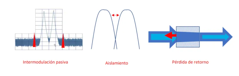
· Passive Intermodulation (PIM)
· Isolation
· Return Loss
SPINNER's passive components are designed to mitigate interference and thus provide the system with:
LOW PIM, HIGH ISOLATION, LOW VSWR
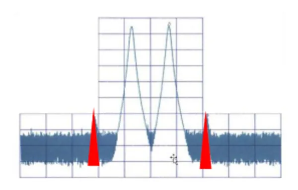
PASSIVE INTERMODULATION
· Metal oxides, contact areas, and ferromagnetic materials have non-linear properties.
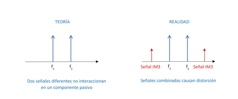
· The PIM effect always appears when at least two different frequencies are transmitted from a passive component, such as a connector or coaxial cable. The component's non-linearity can cause a distortion signal to appear in the frequency range of a useful signal (the receive band is even more critical).
· Non-linear effects can be caused by poor design, manufacturing inaccuracies, defective materials, poorly finished surfaces, and even impurities in the materials or assembly process failures.
· The most important distortion products are the third-order intermodulation products, commonly called IM3.
IM3 is expressed in dBc (dB relative to carrier): using two 20 W carriers (or equivalently 43 dBm).
Optimal IM3 levels should be ≤ -160 dBc
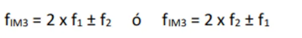
. IM3 frequencies:
• SPINNER already warned about the PIM effect in the early days of the mobile communications era.
• SPINNER dedicates significant effort and resources to developing low-PIM products and conducting factory measurements.
Design + materials + manufacturing = low-PIM product
. • IEC 62037-1 recommends that PIM measurement systems be at least 10 dB better than the PIM value of the component being measured (DUT).
Measuring an antenna specified with IM3 < -150 dBc with 2 x 20 W requires a test setup with all components better than -160 dBc.
• Accurate PIM measurements require a professional end-to-end measurement system.
MEASURING PASSIVE INTERMODULATION
What measurement range are we dealing with? Or, in other words, what range does PIM distortion affect the overall efficiency of our communication system?
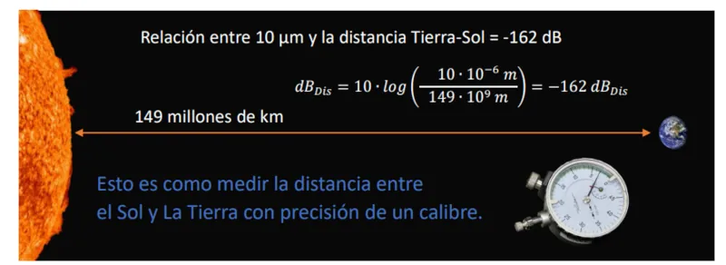
To give you an idea of the range, I'll draw an analogy between a distance of just 10 μm and the distance from the Sun to the Earth. That ratio would be -162 dB, similar to a good PIM value.
If we do the same with a pair of 20W signals and want to obtain a PIM of -162dBc, what would the power of IM3 have to be?
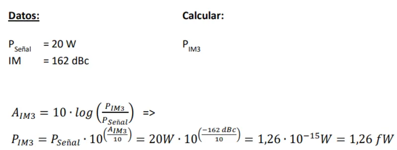
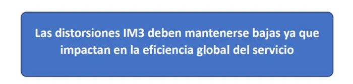
We're talking about a very low signal (1.26 femtowatts) to avoid passive intermodulation problems. As soon as the IM3 signal power starts to increase above that value, we'll begin to have problems, and the efficiency of our mobile communication system will be reduced.
ISOLATION

• Isolation is defined as the interference (crosstalk) between two channel signals.
• Interband isolation occurs between different signal bands (such as 5G 700 and LTE 800).

• Intraband isolation occurs between different operator signals in the same band

The level of isolation achieved depends on the quality of the component used:
Good couplers have isolation of up to 30 dB;
good combiners have isolation of up to 50 dB.
"The greater the isolation, the better the overall efficiency of the system."
VSWR LOSS

Whenever a signal is applied to a passive component, a certain amount of the signal will pass through (transmission), another part is absorbed within the component (transmission loss), and a third part is reflected back to the source. The reflected power is known as return loss or VSWR (Voltage Standing Wave Ratio).
The formula that relates return loss to VSWR is as follows:
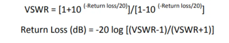
This reflection occurs with every mismatch between components or within the same components due to different impedances.
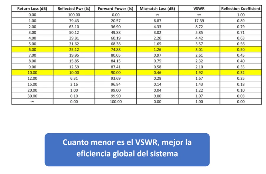
The best VSWR would be 1.0, which means that nothing is reflected and 100% of the signal is transmitted.
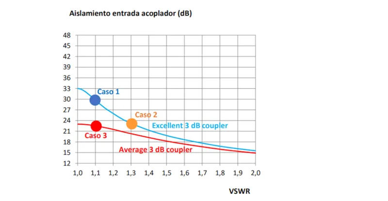
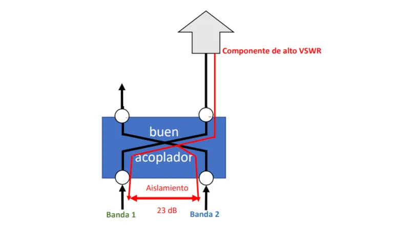
RELATIONSHIP BETWEEN RETURN LOSS (VSWR) AND ISOLATION
· Case 1: Connecting a component with low reflection (VSWR = 1.1) to an exceptional coupler, the isolation can be up to 30 dB
· Case 2: Connecting a component with high reflection (VSWR = 1.3) to the same coupler as above, the isolation can drop to 23 dB
· Case 3: While if you connect a component with low reflection (VSWR = 1.1) to a worse coupler, the isolation can again be 23 dB
In summary, the total efficiency of the system is affected by the performance of the worst component in the system.
Reflections occur in every discrete component throughout the entire distribution network. The closer to the source, the more critical the reflection, reducing the overall system SINR.
GOOD NETWORK PERFORMANCE STARTS WITH GOOD ISOLATION.
For the deployment of passive distributed antenna systems (DAS) to provide indoor coverage for all types of infrastructure, we recommend using our multi-band, multi-operator combining systems. These systems are integrated and factory-tested, providing the best level of isolation on the market and ensuring optimal network performance compared to using multiple discrete components.
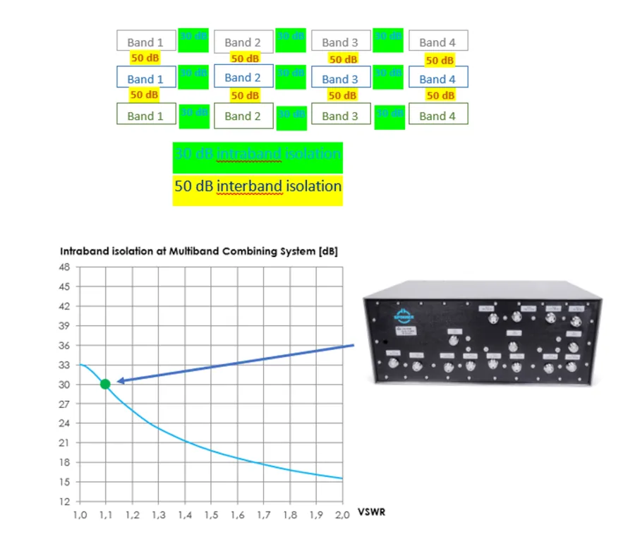
Example of a SPINNER combiner for 3 operators and 4 bands each:
· 30dB interband isolation (between different bands of the same operator)
· 50dB intraband isolation (within the same band between the 3 operators)
Example of a 12x3 combining system for 3 operators and 4 bands each up to LTE
: 12:3 Combining system 700-900/1800/2100/2600 MHz 4.3-10 female - BN: 572660 - Product Finder SPINNER GmbH.
Example of a 15x3 combining system for 3 operators and 5 bands each up to 5G (3600MHz band):
15:3 Combining system 700-900/1800/2100/2600/3800 MHz 4.3-10 female - BN: 570297 - Product Finder SPINNER GmbH
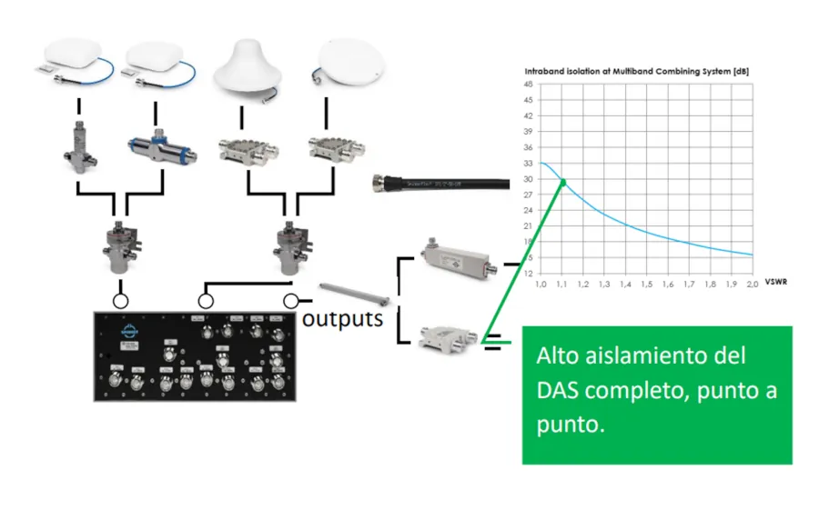
And it continues with the best possible VSWR for each component throughout the network,
which translates into high isolation of the entire system. There's no point in installing a high-quality combiner if we deploy coaxial components and jumpers with poor return loss throughout the network, since, as we've seen, this will reduce the overall isolation and efficiency of the system.
Conclusion: OVERALL SYSTEM PERFORMANCE
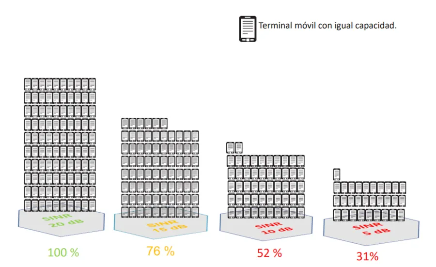
The Signal-to-Interference-Plus-Noise Ratio (SINR) is commonly used in mobile communication systems to measure signal quality.
SINR is a value used to provide a theoretical upper limit for channel capacity (or data transfer rate) in a mobile communication system.
Example: Rx = -90 dBm; Rx noise = -110 dBm => SINR = 20 dB
. The following table shows the reduction in efficiency (system capacity) when we set the SINR value of 20 dB as the reference for 100% system efficiency.
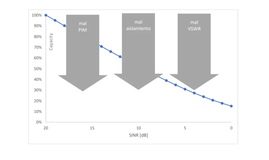
The higher the SINR,
the more efficient our network is.
The greater the capacity per user.
The greater the number of users supported.
The following diagram shows how network capacity varies as the SINR value decreases, meaning that fewer terminals can be connected while supporting the same network capacity.
At SPINNER, we have been experts for over 75 years, manufacturing very high-quality components to provide maximum efficiency for your mobile communications network, including the next-generation NEX10® connectors (connectors, adapters, coaxial jumpers, and calibration kits for VNAs).
RF components - Product Finder SPINNER GmbH
Author: Alejandro Fernández Gálvez, Senior Telecommunications Engineer from the Polytechnic University of Madrid (UPM) – Sales Manager Spain & Portugal at SPINNER.


 Farnell is now distributing Toshiba's new high-power SPDT (unipolar monodirectional) RF antenna switch.