 To ensure signal integrity and product reliability, it is essential to identify the electrical, mechanical, environmental, and application-specific limitations that may affect the overall performance of the cable.
These variables have a direct impact on the materials used for the cable dielectric and sheath, as well as the cable construction.
Furthermore, testing and data analysis are essential to ensure that the cable will perform reliably in a specific environment.
Identifying Limitations:
Environmental influences are having a greater impact on RF/microwave cable assemblies. Electrical performance is probably the first and most important consideration, and many factors can compromise signal integrity, such as internal and external electromagnetic interference (EMI), VSWR, and insertion loss. Electrical performance is usually very reliable when no other environmental factors are involved; however, when mechanical, environmental, or application-specific stress is added, maintaining reliable electrical performance can be more difficult.
Mechanical stress occurs when cables are exposed to various types of movement. Bending creates kinetic energy in the cable, which can cause serious damage if not properly managed. One of the biggest causes of mechanical stress in cables occurs when the cable is part of equipment operated by a person. An operator can bend, pinch, or crush a cable by stepping on it or wrapping it around it.
Therefore, tensile and crush resistance are essential for overcoming mechanical stress. Furthermore, cables used with portable equipment can come into contact with sharp surfaces that can cut or abrade them. When the added complexity of compensating for vibration or gravity is factored in, mechanical stress can significantly compromise stability and cause premature cable failure.
Results of environmental stress in the physical area where cables are used:
- Extreme temperatures and pressures affect cable materials. Low temperatures make them brittle, and high temperatures make them very delicate.
- Spills or drips of oils and additives from a cable can contaminate a cleanroom during a manufacturing process, while hydrostatic pressure can cause gases or liquids to impregnate the cable jacket. Radiation can damage dielectric materials and the cable jacket depending on the type and dose level. Friction from moving a cable can compromise the cable jackets, causing particle formation, while contaminants such as mud, chemicals, or metal particles can damage the cable coating. Environmental stress can significantly compromise dielectric materials and the cable jacket, so these issues must be considered when designing an assembled cable.
Results of application-specific stress due to limitations that are unique to the application in which the cable will be used:
In aerospace applications, cables need to be as small and lightweight as possible to minimize mass during liftoff. If the cables are used by technicians or other personnel, safety issues such as flammability, tension, and halogen use are factors to consider.
One of the complexities of cable assembly design is that electrical, mechanical, and environmental performance are interrelated. Each has a direct impact on the others, so the design must be thoroughly tested in the specific application.
Choosing the Right Materials:
Ensuring stable, high-quality signal means evaluating dielectric and sheathing materials for attributes that must be considered in harsh application environments. The dielectric materials used in signaling cables affect signal integrity as well as cable robustness. The material used in an outer jacket affects the maximum voltage and abrasion resistance. Sheathing materials must withstand most external factors (e.g., temperature, friction, liquids, and gases) to protect the conductors inside the cable. The list of possible materials used in cable dielectrics and sheathing is very long, and many have been developed for specific applications. Since each material has unique properties, some are more suitable than others for use in microwave cables designed for demanding environments.
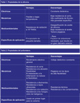
Silicone.
Silicone is mainly used as a cable coating and is very flexible even at low temperatures, Table 1. However, it cuts easily, and its sticky surface has a high coefficient of friction, so it is not good for cleanroom environments.
Silicone has low tensile and breaking strength, therefore it needs to be thicker compared to other coating materials. Some surface treatments exist to reduce the coefficient of friction, but these tend to wear off over time. Silicone has very good radiation resistance, but the grades of silicone used for cable coating are known for their silicone oil outgassing in pouring applications such as a thermal vacuum chamber. If weight is a concern, silicone is not the optimal choice.
If flexibility is important and weight isn't a concern, silicone is a good option. However, it requires more effort to access the conductors, which translates to higher termination costs.
Polyurethane
is a good coating material, but it is not used as a dielectric material because its dielectric strength is low compared to other materials (Table 2). Halogen-free versions are available. Mechanically, polyurethane is flexible and highly resistant to cutting and abrasion. Flame-retardant treatment does not reduce flexibility; however, the more flexible types tend to be sticky or viscous, resulting in a higher coefficient of friction. Environmentally, polyurethane is resistant to solvents, ultraviolet rays, radiation, and fungi. Polyurethane does not have a very wide temperature range; it becomes brittle around -40°C, and its maximum temperature limit is around 100°C. Furthermore, it is not resistant to commonly used cleaning chemicals.
Polyethylene
is more suitable as a dielectric for conductors, as polyethylene jackets tend to be rigid, which affects cable flexibility (Table 3). Polyethylene has good, consistent dielectric properties when used with foam. Mechanically, polyethylene is high molecular weight, abrasion-resistant, and has low friction, yet it is also strong compared to other materials. As with polyurethane, the temperature range of polyethylene is rather limited, and it is difficult to bond chemical tubing to polyethylene cable jackets. In general, the mechanical properties of polyethylene are reduced by flame-retardant treatments.
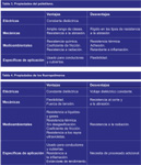
Fluoropolymers
Fluoropolymers such as fluorinated ethylene propylene (FEP), perfluoroalkoxyalkanes (PFA), and polytetrafluoroethylene (PTFE) are excellent sheathing materials, especially in applications where the cost of system failure is high, Table 4.
The dielectric strength of fluoropolymers is among the highest of any dielectric material. Fluoropolymers can withstand extreme temperatures, but each material has its own range: FEP can operate at temperatures from -250°C to 150°C, while PFA ranges from -250°C to 200°C.
PTFE is suitable for cryogenic temperatures of 260°C without losing flexibility. Fluoropolymers can also withstand exposure to harsh chemicals, acids, and solvents, and are inherently non-flammable. PTFE and its copolymers also offer the benefit of low gas emission, which is critical for ultra-high-pressure (UHV) environments. Many fluoropolymers are flexible, but like temperature resistance, flexibility varies depending on the specific material. PFA is the most rigid, followed by FEP and PTFE, with treated PTFE being the most flexible. Anything added to the cable's dielectric sheath, conductors, or shielded conductors will degas under vacuum. When materials degas, suspended particles condense on cooler surfaces, which are typically the working surfaces in the application area. In a satellite, optics can become fogged by silicone oil or other processing lubricants that degas from the cable. PTFE is chemically inert and contains no processing additives, oils, lubricants, or plasticizers, making it the best material for vacuum environments.
Treated Fluoropolymers:
One of the few drawbacks of fluoropolymers is their limited resistance to abrasion and cutting. Certain fluoropolymers can be treated to improve their physical, chemical, and electromagnetic properties, enhancing the cable's ability to withstand the specific challenges of a microwave application. Ethylene tetrafluoroethylene (ETFE) can be irradiated to improve its mechanical properties and chemical resistance; however, irradiation increases stiffness, resulting in a significant decrease in flexibility. PTFE is heat-resistant and chemically inert, so its temperature and chemical properties remain unchanged when treated to improve its electrical or mechanical attributes.
Specialized technologies have been developed to treat PTFE so that it can withstand a wide variety of environmental and mechanical challenges (Table 5). The dielectric material used to insulate the conductors can significantly affect insertion loss, cable size, and flexibility. The lower the dielectric loss, the lower the insertion loss the cable will exhibit. Typical fluoropolymers have a dielectric loss of 2.1. To reduce cable size, PTFE can be treated to have a dielectric constant of 1.3. At the same time, the dielectric constant can be increased by a factor of 2.5, while achieving a very low loss tangent of 0.00015 at 10 GHz compared to standard PTFE manufacturing. With these attributes, a conductor insulated with a 1/2000th-inch (50-micron) treated PTFE layer can be rated for use at 1,000 V. Another version of treated PTFE can be made semiconducting and used to increase the effectiveness of cable shielding. For abrasion or shear resistance issues, PTFE has been engineered to achieve a tensile strength 50 times greater than standard PTFE and withstand cryogenic temperatures up to 300°C.
Verifying the Design:
Some industries have defined safety, environmental, and performance standards for cables, but many robust applications using microwave cables require going beyond these standards. In these situations, the manufacturer may need to develop additional tests that evaluate the cable's electrical performance while simulating mechanical and environmental stress similar to that of the application. It is essential to monitor electrical performance and signal integrity throughout all tests, and the specific type of test required depends on the application's environmental constraints.
Multi-stage applications require close monitoring of each stage across multiple assemblies of the same type and length to minimize residual systemic error. These errors eventually affect system range, resistance to interference and disturbances, and overall accuracy. Tracking problems at each stage most often arise from either poor material quality and process control during cable assembly manufacturing or from combining components from different manufacturers within the assemblies. Therefore, stage tracking and stability must be carefully tested in the environment where the cables will be used.
Mechanical testing verifies electrical performance while the cable is operating under environmental conditions such as crushing, abrasion, potential shear, high bending, continuous flexing, shock, and vibration. The use of microwave/RF cables generally means the application requires excellent phase stability, which can be affected by bending and flexing during installation, routine maintenance, or normal use. Accidental bending is a frequent problem with handheld test instruments because the cable assembly is often wrapped around the instrument for transport. The impact of these movements on system performance must be evaluated during system design. In a laboratory setting, a technician might wrap the cable around a chair, meaning shock force is also a concern. Accidental bending during movement is difficult to recreate in a test laboratory, but the worst-case scenario can be simulated using a tick-tock test with repeated bending of 180 degrees or more. A tensile test can then be performed to simulate a cable being used as a restraint strap. During these tests, insertion loss and ROE should be evaluated.
The electrical performance of the cable must be measured while simulating the environmental conditions in which it will operate—conditions such as temperature, altitude, and pressure extremes; vibration and acceleration; exposure to liquids or gases; and humidity. It is important to monitor impedance during altitude changes, shocks, and vibration tests. Vibrations and shocks can cause mechanical and electrical failure due to metal fatigue or cracks in the welds. Temperature changes have a direct impact on phase length. As the temperature approaches an extreme, the electrical length will change, and if it does not change at the same rate as the temperature when it returns to normal (a state known as hysteresis), it is very difficult to apply error correction techniques to the signal. Adding a clamping force during a temperature cycling test allows monitoring of the cable's dielectric strength to observe how the jacket and conductor change.
After the cable undergoes in-depth mechanical and environmental testing, the manufacturer must re-verify that the electrical performance, and the dielectric and sheath materials remain stable within the application requirements.
For products used in the most demanding environments, the consequences of cable failure are generally severe. Therefore, ensuring the electrical and mechanical integrity of cables is essential for the application's lifespan. This involves understanding the factors that can affect cable performance, selecting appropriate materials to withstand these factors, and verifying cable reliability through electrical, mechanical, and environmental testing.
Author:
Paul Pino, applications engineer at WL Gore&Associates, Inc.