
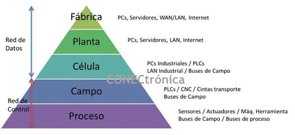
 Figure 1 shows the hierarchical pyramid structure of industrial communications, based on the location, number of elements, and functionality (data or control). It should be noted that at the base, there are numerous industrial automation elements capable of sending small amounts of information. As you move up the pyramid, the number of elements decreases, but the amount of data to be communicated increases.
The response time required of the communication subsystem at each level of the CIM (Computer Integrated Manufacturing) pyramid can vary from a few microseconds for the process or field level, to seconds for the plant level, thus positioning differently the type of communication network needed to implement said communication.
Control networks are linked to the lower levels of the CIM pyramid because they must be able to support, in real time, information traffic consisting of a large number of small packets originating from a smaller number of stations than data networks. The separation between the two networks is not as clear as it might initially seem, since data networks tend to be given characteristics typical of control networks, as is the case with Profinet.
Industrial networks are currently experiencing significant progress in terms of new communication methodologies supported by technological development. Numerous standards and a variety of brands are also emerging around new technologies, making the market very diverse and expanding the possible communication solutions in industrial environments.
When integrating a process or production line, it's common to see that each manufacturer develops its own programming environment and physical component characteristics, either adhering to a standard or creating its own proprietary design. Often, a large industrial automation manufacturer develops a proprietary design that, within a few years, becomes a de facto standard used by numerous companies. Currently, the most common approach is to form a consortium or association of companies that define the system's characteristics, providing a framework and design documentation. These are the working groups of various associations dedicated to system standardization.
2. Profinet-Based Networks
In 1989, the Profibus protocol was developed to allow users to interconnect equipment from different manufacturers. According to the ISO/OSI model for Layer 1 (physical layer) communication protocols, it uses the RS485 standard. Today, Profibus has approximately 20 million nodes installed worldwide and has proven to be one of the best fieldbuses. However, the market demanded further advancements, leading to the creation of the Profinet standard: an industrial communication bus based on Industrial Ethernet.
![]()
Profinet uses standard IEEE 802.x (Ethernet) telegrams with priority information. The Profinet frame has the structure shown in Figure 2, which indicates whether it is a Profinet datagram. This allows switches to manage data transmission in real time by applying prioritization mechanisms.
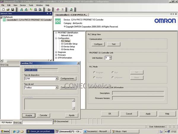
2.1. Profinet Software
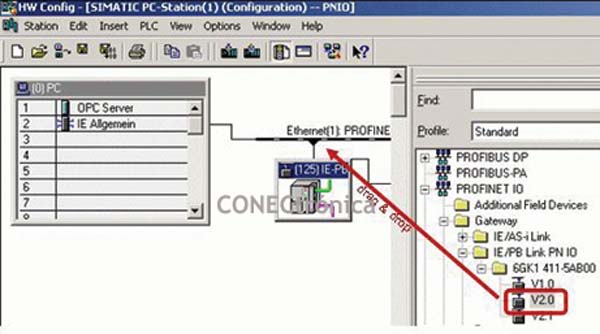
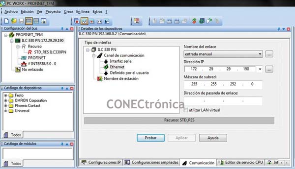
The main Profinet device manufacturers offer users an optimized GUI (Graphical User Interface) for configuring a Profinet network. The integration software performs network configuration, device parameterization, program download, and diagnostics for both the network and its constituent devices (Figure 3).
Some Profinet integrator configuration, programming, diagnostic, and/or monitoring tools include:
2.2. Hardware in Profinet
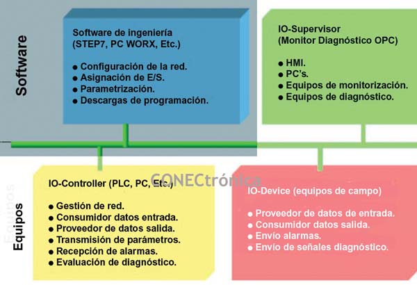
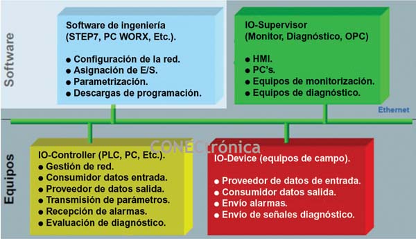
For the direct connection of decentralized field devices to Industrial Ethernet, PROFIBUS International has defined the Profinet-IO standard. This standard allows field devices to cyclically transmit their data to the corresponding controller. Profinet-IO defines the following types of devices:
- IO-Controller: a controller (e.g., PLC) on which the automation program is executed.
- IO-Device: a decentralized field device assigned to an IO-Controller.
- IO-Supervisor: a programmer/PC with commissioning and diagnostic functions or an HMI4 device. The field device reads signals from the peripheral and transfers them to the IO-Controller. The controller processes these signals and transmits the output signals back to the IO-Device.
Figure 7 illustrates the characteristics of the three Profinet-IO groups mentioned.
2.3. Interoperability via GSDML Files
. Profinet uses a Master/Slave model. During startup, the Master establishes a connection with the Slave devices and writes the startup parameters to the corresponding devices. The cyclic data exchange then begins. The Profinet controller (Master) receives all the configuration information through a configuration tool. This tool reads the necessary information from the device's GSDML file.
GSDML files are Generic Station Description (GSD) files written in XML format. They describe the characteristics of the Profinet device model, enabling interoperability between different device brands. This file contains all the properties of the Profinet field devices that are relevant for the cyclic data exchange.
The GSDML format is not intended to describe the technological functions or graphical user interface of a device. For this purpose, an engineering tool that allows device integration (such as PCWorx, CXProgrammer, or Step7) should be used.
In upcoming articles, we will cover the configuration of a Profinet network from various configuration and integration systems.
1 The Open Systems Interconnection (OSI) model (ISO/IEC 7498-1) is also known as OSI.
2 RS485 is a multipoint differential transmission bus using two untwisted, shielded wires.
3 Industrial Ethernet is the name given to the use of the Ethernet protocol in an industrial environment for automation and control of production machinery.
4 HMI stands for Human-Machine Interface. HMI systems can be seen as a visual representation of a process. This representation can be on special devices such as operator panels or on a computer.


