
 Factory-assembled trunk systems with MPO multi-fiber connectors are increasingly preferred for optical cabling system deployments, especially in high-density areas such as data centers. To maintain bidirectional transmission paths, the system must provide correct polarity to ensure each transmitter (Tx) connects to its corresponding receiver (Rx) at the other end.
MPO connectorization of ribbon cables requires specific considerations regarding the design, maintenance, and reconfiguration of the cabling system. The ANSI/TIA-568-B.1-7-2006 standard, Commercial Building Telecommunications Cabling Standard, Part 1 - General Requirements, Addendum 7 - Guidelines for Maintaining Polarity Using Array Connectors, has been approved and published to provide guidance on maintaining polarity when using MPO connectors, offering three working methods. This document discusses each of these methods.
The standard provides three guidelines for establishing correct polarity between the transmitter (Tx) and receiver (Rx) using multiple patch cords with MPO connectors. A typical system would consist of:
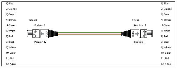
• Pre-terminated trunks with 12-fiber MPO connectors
• MPO-to-duplex connector or coupler transitions, such as modules or cassettes
• Duplex patch cords for connecting the cabling system to the transmission equipment
Each 12-fiber MPO connector (6 duplex circuits) connects to a transition (cassette or multi-patch harness) at each end, where the patch cords connect to the couplers and active equipment. All connectors and couplers in the system have locking mechanisms that ensure correct orientation upon insertion. While the locking mechanism ensures correct MPO orientation, it does not guarantee that the polarity of each fiber pair is maintained. This is why it is necessary to implement methods A, B, or C of the TIA standard; each of these requires a specific combination of three components to maintain the polarity of the transmission system.
Method A: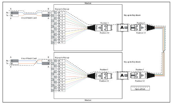
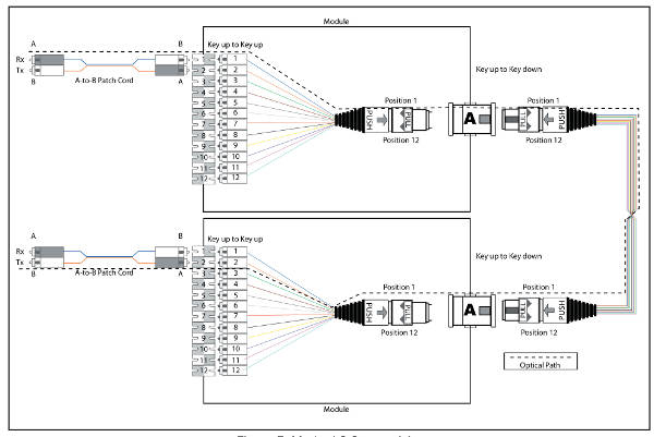
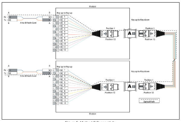 Method A uses straight-through type A trunks connected to transitions with type A MPO adapters. All ring components are connected with a key-up/key-down locking mechanism. One end of the link uses straight-through AB patch cords to connect the respective duplex ports of the transceivers. The other end requires cross-linked AA duplex patch cords for connection to the transceivers. See Figures 1 and 2. Each optical path contains only one AA patch cord. In this connectivity system, the final pair orientation ("pair flip") is determined by the patch cord. This connectivity method is very efficient.
All AB patch cords must be placed at the same end of the ring, ensuring that the A_B and A_A patch cords are clearly distinguishable. The trunks can be linked without any special polarity considerations. Angle-polished MPO SM connectors can be used. Method A is easy to install and the most widely used worldwide.
 Method B:
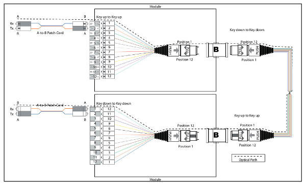
Method B uses direct Type B trunks connected to Type B MPO couplers. All ring components are connected key-up to key-up. Direct AB duplex patch cords are installed at each end. See Figures 3 and 4.
This method establishes a physical link from position #1 at one end to #12 at the other. One of the transitions at either end must be inverted to achieve #1 to #1 routing; therefore, two different transitions are required: one normal and one inverted. This method does not allow the use of MPO connectors, which limits its application.
 Method C:
Method C uses C-type trunks with pair crossover, connected to MPO-type A couplers. All system components are key up/key down. Each end has AB (straight-through) patch cords to connect to the transceivers. See Figures 5 and 6.
In this method, the trunk provides the pair flip directionality; it is a consistent system, but requires special attention when daisy-chaining trunks; AA patch cords may be necessary to maintain polarity. It allows the use of APC SM connectors. It is not widely used, as it requires careful planning.
All the interconnection methods described share the same objective: to ensure that the TX port of one device connects to the corresponding Rx port at the other end. Each method requires a specific combination of components to maintain system polarity, as detailed in the table:
![]()
It is recommended to select one of the connectivity methods and use it preferentially, without mixing or combining the different components of each method. Your system may not function. Ensure that each and every component is clearly labeled, identified, and tested.
Translation of the article “logica sistemi MPO” by Brand Rex, translated and provided for publication by the firm COFITEL.


