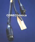
 Modern military operations are characterized by intensive communications and rely on high-speed computing equipment, from handheld radios and advanced headsets to weapon command systems, missile guidance, and avionics. Effective protection against electromagnetic interference (EMI), radio frequency interference (RFI), and electrostatic interference (ESI) is vital.
Cables are a highly vulnerable entry point for interference; therefore, manufacturers employ a number of established techniques to ensure proper cable shielding and shield termination. Given the increasing importance placed on weight, size, and cost savings in military equipment, as well as in commercial avionics applications and other high-value equipment such as medical scanners, there is a growing demand for suitable lightweight alternatives that are easier and faster to assemble and better suited for repair and maintenance.
Shielding Effectiveness
: Shielded cables contain radiated interference and protect signals against external EMI, RFI, and ESI. A well-designed cable comprises many crucial, independent components and has become as vital an aspect as any other when designing a system. Its effectiveness is expressed in dB, as the ratio between the incident wave's field strength and the permissible field strength. Shielding can reflect or absorb (with grounding) radiated electric or magnetic fields.
Four sources of signal interference are distinguished:
- Static noise when an electric field distorts the signal
- Magnetic noise from high-power AC motors or transformers, which can generate reverse current flows
- Common-mode noise resulting from current flows between different potential masses distributed among various points within the system
- Crosstalk, referring to standard AC signals between two or more nearby wires or cables
Since EMI/RFI problems can occur along the entire cable and at the contact between a cable and its connector, the quality of both the shielding and the termination is extremely important. In practice, more problems are observed at the connection terminations than anywhere else on a cable.
Materials and Terminations
: Common shielding and termination methods include using a metal or metallized plastic connector and soldering the connection between the cable shield and the connector. Alternatively, the connection can be wrapped with copper tape, which is then soldered to the cable shield. While these solutions are certainly effective, they are also expensive and labor-intensive and can result in inconsistent shielding.
Other types of shielded cable feature an aluminum/polyester or aluminum/Kapton foil that completely covers the conductors. The foil is in continuous contact with a spirally wound tinned copper drain wire, which creates an electrical connection between the shield and the circuit ground. The foil metallization is typically very thin, around 0.75 mm, providing relatively high resistance compared to other shielding materials, such as braided wires. Therefore, braided shielding is often used when superior protection is required.
Braided shielding consists of a mesh of copper wires interwoven to form a strong yet flexible cylinder. The wires can be bare, tinned, or silver or nickel-plated. Depending on the type of connector used, it may be necessary to untwist or loosen the braid to terminate the shielding. Terminating coaxial connectors, however, is particularly simple and preserves the shielding all the way to the connector housing. (Multi)braided shield cables are high-quality cables that provide a minimum shielding coverage of 85%.
In some cables, the braided shielding can be coated with a layer for more effective shielding. This coating prevents gaps between the braided elements, because even a tiny hole can be a window for high-frequency noise. Braided shielding has the disadvantages of being heavier and less flexible.
Cables with copper- or nickel-coated fabric shielding can be used as a thin, lightweight, and highly flexible barrier that provides adequate environmental protection in harsh environments, typical of military and aerospace applications.
Limitations of Conventional Armored Cables:
Conventional armored cables are vulnerable to tearing or shedding of the shielding during repair or maintenance. This can render the entire cable unusable.
Furthermore, the use of large quantities of armored cables in aircraft or ground vehicles can significantly increase their overall weight, which in turn can negatively impact agility and fuel consumption. This is an undesirable effect in both civilian and military applications and runs counter to other weight-saving initiatives, such as the increasing use of structural carbon fiber. Large quantities of metal-armored cables can also lead to undesirable increases in size, weight, and cost in many other high-performance equipment, such as medical scanners.
The radio frequencies prevalent in avionics systems are also a factor that is currently increasing the demand for shielding capable of operating at extremely high frequencies.
Heat Shrink Tubing:
Conductive heat shrink tubing (Figure 1) can help engineers address the challenges of maintenance, weight, and high-frequency shielding by providing lightweight, fully enclosed EMI shielding combined with mechanical/environmental protection for wire and cable bundles. This solution can deliver weight savings of 40% to 65% compared to conventional braided mesh-based shielding systems, while also contributing to reduced labor costs.
The outer layer of heat-shrinkable polyolefin tubing is resistant to abrasion and chemicals. An inner layer of conductive silver ink is applied, providing EMI shielding and grounding. Various grades of polyolefin with diverse environmental and electrical properties are available to suit different applications, including military and aerospace systems. Heat-shrink tubing is typically applied during the initial assembly phase of products, but it can also be used as an ideal method for adding secondary insulation and additional EMI protection to electrical systems already in service. It is used in conjunction with familiar techniques and tools for applying standard heat-shrink tubing.
To create lightweight, high-performance shielding for a complete wiring harness, a comprehensive heat-shrinkable EMI shielding system, such as CHO-SHRINK® 1061, is required. In addition to its conductive-coated tubing conforming to MIL-R-46846, Type 5, this system also includes continuity and transition elements, grommets, cable ties, and a hot-melt conductive insulator/adhesive. This system offers a high degree of protection and sealing, 360-degree EMI/RFI/ESI shielding, 70 to 80 dB attenuation at frequencies above 500 MHz, and flammability characteristics compliant with UL VW-1 and CSA OFT. The materials also meet NASA outgassing specifications, making them suitable for use in space applications such as satellites.
Complete Shielding System:
Engineers can use the various components of this system to fabricate a complete, sealed wiring harness with properly terminated shielding on all connectors, without the need for soldering.
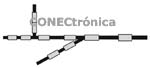
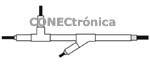
The recommended method is to run the wiring with all branches in place and plan where the cable clamps or connector-to-cable transitions should be attached. Continuity elements are placed at these points and securely fastened to the wire bundle, as shown in Figure 2. These elements are metallized on their outer surface.
The next step involves placing pre-cut lengths of the conductive tube, which is metallized on the inside, onto the continuity elements, leaving a small portion of the conductive surface exposed at each end. Heat is then applied to shrink the tubes, and the transition elements are subsequently installed at the branch intersections of the wiring. At this stage, the wiring is correctly aligned and encased in the protective shield, as shown in Figure 3.
The connectors are now installed and terminated using CHO-SHRINK cable glands and cable ties. The cable ties are applied last and are placed over the wires of the housing (or adapter) at the connector end and over the exposed metallized continuity surface at the cable end.
CHO-SHRINK cable ties are supplied with a hot-melt, high-conductivity adhesive/insulator pre-applied to each opening, which flows during shrinkage to provide an effective environmental seal without compromising the EMI shielding characteristics. Shrink-fit adapters and cable ties, which feature a knurled or grooved surface, also serve to improve resistance to torque, pull-out, and breakage stresses.
In conclusion,
heat-shrink cable shielding offers designers greater options and flexibility for a high-performance solution that is lightweight, easy to maintain and repair, and suitable for use in a variety of military and civilian environments and applications. A complete shielding system that includes all the necessary components to construct a sealed and shielded wiring harness effectively minimizes assembly time and ensures optimal levels of performance and reliability.
Author:
Christophe Loret, Product Manager for Conductive Compounds, Chomerics Division Europe