
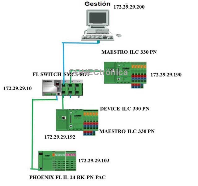
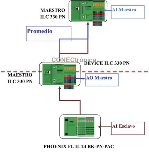
Figure 1 illustrates the topology to be implemented and assigned IP addresses.
2. Lower Level Master
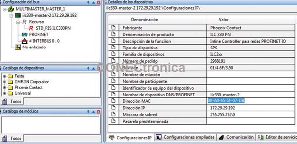
In the “IP settings” tab of the master (ILC 330 PN, Figure 2), it is necessary to update the Name, MAC Address, IP Address and Subnet Mask of the lower level master PLC.
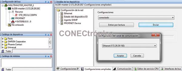
For the lower-level Profinet Master, it is necessary to activate the "IO Device" service so that it can be treated as a Profinet-IO device by the higher-level Master. This service allows master devices to create I/O tables to exchange information on the Profinet network. On the "Extended Configurations" tab, in the "IO Device Status" section, select "Connected" from the "Configurations" drop-down menu, click "Send," and select the PLC of interest to activate the service. This is illustrated in Figure 3.
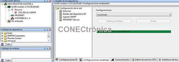
If the IO Device service is working correctly, the message “service running successfully” will be displayed on the screen, and the device will be shown as connected in the “Settings” section. Figure 4 illustrates this.
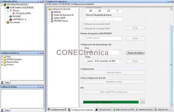
In the “Ethernet” section of the “Extended Settings” tab (Figure 5), it is necessary to activate the network configuration by using “Reset Control” to apply changes to the network and allow the lower-level Profinet Master to be seen as an IO Device (slave) by other masters present on the network.
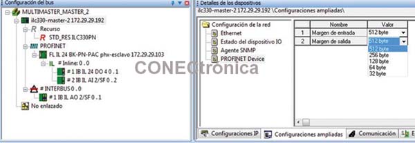
In the “Extended Configurations” window, under “Profinet Device”, it is possible to configure the size of the input and output tables for data exchange with other PLCs in Profinet mode. This option allows you to optimize the data flow on the network according to the transmission needs. The table sizes available in the ILC-330PN PLC are 512, 256, 128, 64, and 32 bytes, as illustrated in Figure 6.
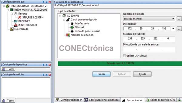
The “Communications” tab allows you to test communication with the PLC. If the parameters are correct, the message “ILC-330 PN host type” will be displayed on the screen (Figure 7) in green.
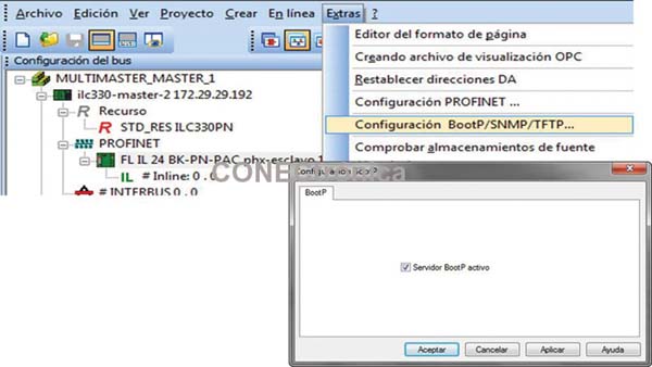
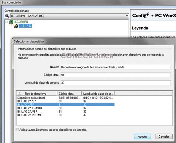
After activating the BootP service in PcWorx, the bus can be read to add the modules connected to the PLC. Activating the BootP server is illustrated in Figure 8.
With the BootP server activated, in the “View”- “Connected Bus” option of the main menu it is possible to add the modules installed in the PLC (Figure 9).
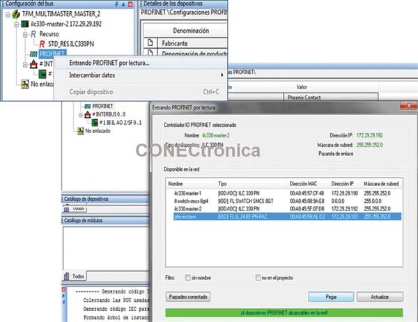
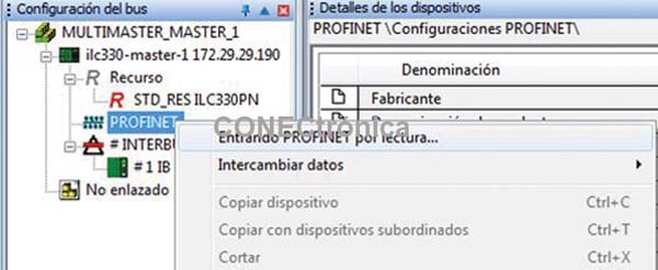
By selecting “Entering PROFINET by reading” in the Profinet context menu of the
Project tree (Figure 10), the Phoenix-Contact Profinet slave FL IL 24 BK - PN PAC appears, and you can paste it into the project tree by selecting the device and clicking on “Paste”.
Once the above procedure is completed, it is possible to develop the application and control program for the lower-level network.
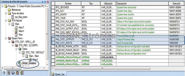
In the "Global Variables" area of the PLC, two arrays can be seen, one for input and one for output, of the selected size (512 bytes). These two arrays are the variable tables for information exchange and will be accessible by higher-level masters in the network.
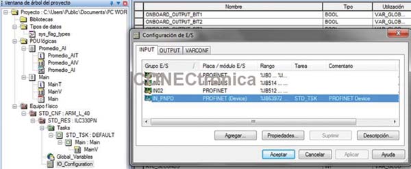
Additionally, in the "Programming Area", under "IO_Configuration" in the
"I/O Configuration" table, the Profinet (Device) service is enabled. This means that the PLC has the functionality to share information with other master PLCs in Profinet mode. This is illustrated in Figure 12.
3. Master Project at the higher level
: The new project has been created and saved, the IP address of the PLC is configured, the address range is set, and the configuration parameters of a Profinet-IO controller are established.
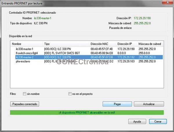
The next step is to add the lower-level master device and any other IO Devices you wish to integrate to the Profinet bus of the higher-level master. Using "Entering Profinet by reading" (Figure 13), you can see the list of reachable devices on the network (Figure 14).
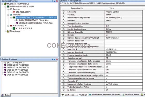
Note that when the lower-level master device is attached, it is added as a slave device (IO-Device) in the project tree, specifically on the Profinet bus. The catalog of available modules for the lower-level master device consists of data arrays with dimensions adaptable to the project's needs. In this case, the EA512 module (512-byte Input/Output Array) is added; the array size must match the dimension established in the project for the lower-level master. This is illustrated in Figure 15.
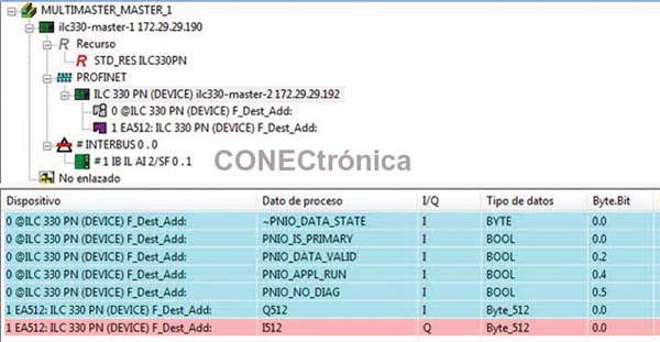
In the data allocation area for the new IO Device (Figure 16), you can see both the 512 Byte input and output arrays, as well as the diagnostic registers of the Profinet header of the lowest level master.
4. Network Integration Test
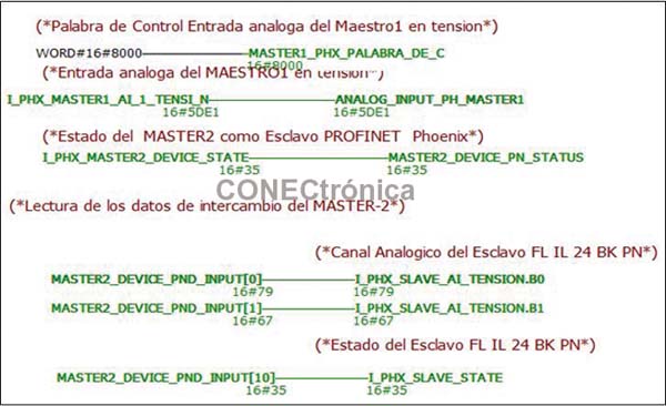
The application program in Figure 17 illustrates the connection of internal variables to the I/O array of the lowest-level master. Initially, the analog module measurement and the status of the Profinet header of the lowest-level master are taken. Subsequently, the data transmitted from the lowest-level master is read; in this case, the analog input measurement and the status of the Profinet header of the Phoenix FL IL 24-BK PN PAC slave connected to the lowest-level master.
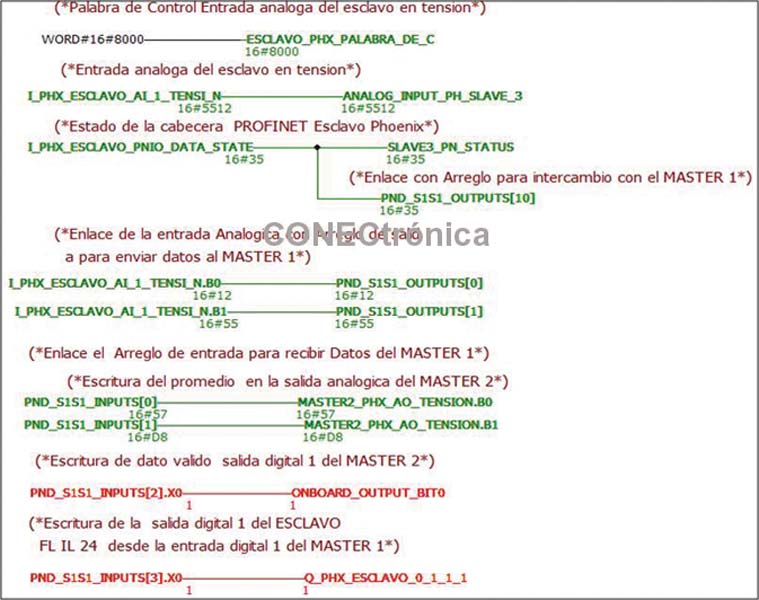
In “Active Debugging” mode (Figure 18), the status of the various signals exchanged with the higher-level master can be seen on the lower-level master.
The flow of analog signal data is illustrated graphically in Figure 19.
5. Conclusions
From all of the above, it is worth highlighting that communication via Profinet between programmable logic controllers (PLCs) is an easy and simple technology to implement, allowing for the
decentralization of the control system and thus resulting in systems with greater versatility, robustness, and flexibility than previous protocols.
Furthermore, it offers the advantage of being a standardized bus, which is why numerous manufacturers in the automation field market Profinet-compatible products.
In terms of interoperability, it can be concluded that adding several slaves from different manufacturers to the Profinet network is a simple procedure, regardless of the master and integration software available. This allows for the implementation of a flexible manufacturing system integrated into a Profinet network with different manufacturers.
In multi-master topologies, interoperability in the Profinet environment is limited, since manufacturers do not provide users with GSDML files for master devices.
This limits the possibility of integrating several masters from different manufacturers into the same Profinet network and necessitates the use of other communication solutions.
Author:
Alfredo Gardel, Ignacio Bravo, José Luis Lázaro, Arley Vanegas


