
1.1. Topology Used
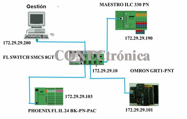
The Profinet network topology is a star network, since the Profinet-IO devices have only one communication port. Figure 1 illustrates the topology to be implemented, along with the IP address assignments.
1.2. Profinet Switch Configuration
As an active communication medium, the “FL SWITCH SMCS 8GT” Communications Switch is available, which allows a copper wired network.
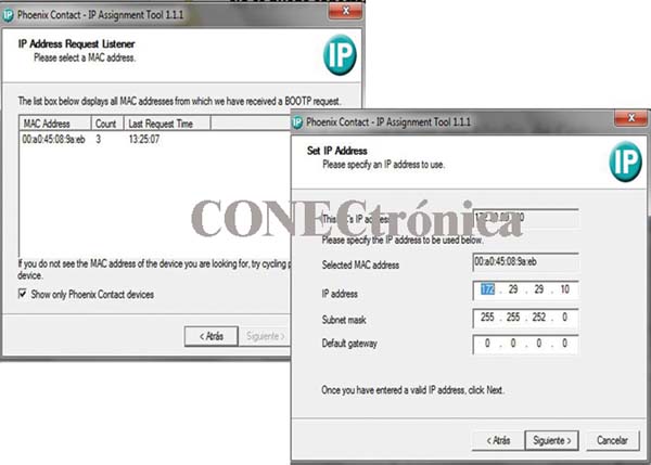
The “IPassign” application is designed to assign IP addresses to Ethernet devices. In the case of the FL SWITCH SMCS 8GT switch, its MAC address can be viewed in the IPassign interface. By selecting the device and clicking Next, it is possible to assign an IP address compatible with the range selected for the Profinet network. The procedure is illustrated in Figure 2.
Once the switch's IP address assignment has been confirmed, you can access its configuration from a web browser and reconfigure both the IP address and the authentication mode. This is illustrated in Figure 3.

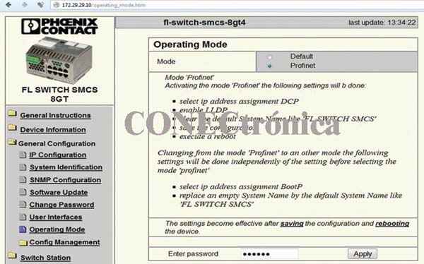
The FL SWITCH SMCS 8GT is an ASIC-compatible device and can therefore operate in real-time mode, enabling a deterministic data communication cycle. This option can be enabled in the "Operating Mode" section by selecting the "Profinet" option, as illustrated in Figure 4.
1.3. Assigning names to Profinet devices
NetNames is Phoenix-Contact's software for assigning names and addresses to devices with the Profinet I/O standard.
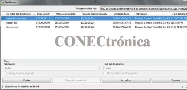
By opening the NetNames software and clicking on "Update", you can see that all Profinet I/O devices are configurable and diagnosable regardless of the manufacturer.
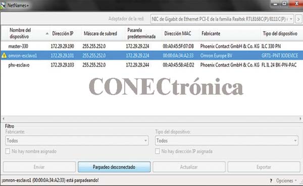
Initially, a name and IP address are assigned to each Profinet device detected by NetNames (Figure 5). The configuration of each device can also be diagnosed using the "blinking connected" option. If communication with the device is successful, this option will cause the diagnostic LEDs on the device to flash.
Once the name and IP address assignment with NetNames is complete, and network compatibility has been verified, the configuration in PcWorx is carried out.
1.4. Creating a Project
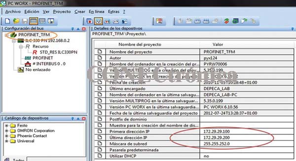
PcWorx is Phoenix-Contact's integration tool for configuring, programming, and diagnosing Profinet-based networks. When creating the project, the master device must be selected. The master acts as a BootP server, for which a range of addresses must be set to authenticate on the Profinet network.
This range is set in the project root in the "First IP Address," "Last IP Address," and "Subnet Mask" fields (Figure 6).
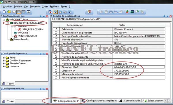
In the “IP settings” tab of the master (ILC 330 PN, Figure 7), it is necessary to update the name, MAC address, IP address and subnet mask of the master PLC.
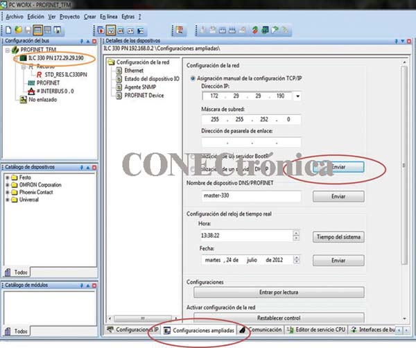
In the “Extended settings” tab, clicking on “Send” saves the new parameterization of the master device to the PLC memory (Figure 8).
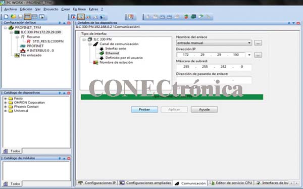
Once the master device has been parameterized and its data sent, the communication between the master device and the programming PC can be verified in the “Communication” tab by clicking on the “Test” option (Figure 9). If communication is successful, the status bar will turn green.
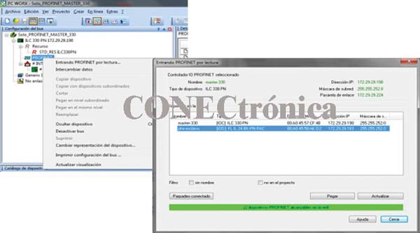
1.4.1. Integration of the Profinet slave
By selecting “Entering PROFINET by reading” in the Profinet context menu of the Project tree (Figure 10), the Phoenix-Contact Profinet slave FL IL 24 BK - PN PAC appears, and can be pasted into the project tree by selecting the device and clicking on “Paste”.
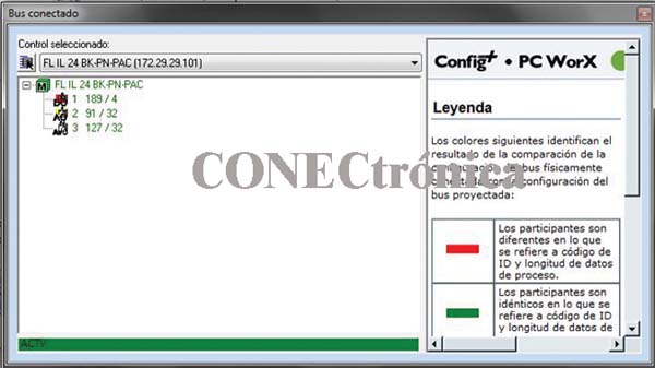
The "Connected Bus" option in the "View" menu allows you to view the local bus of the slave device. From this window, you can add the various modules connected to the Phoenix-Contact FL IL 24 BK - PN PAC Profinet communication header (Figure 11).
The complete configuration of the Profinet network can be seen in the project tree (Figure 12).

By selecting any of the Profinet-IO devices in the project tree, from the “Profinet Device Names” tab, it is also possible to send name and address data to the Profinet devices. This is illustrated in Figure 13.

1.4.2. Data allocation area
In the data allocation area in PcWorx (Figure 14) appear all the variables that represent the devices interconnected by the Profinet network.

All diagnostic records are available in the process data mapping table, making it possible to know the system status, determine the causes of errors, and provide additional information to the program in use.
A large number of diagnostic and control records are available for each device, enabling real-time monitoring of the system status. This is precisely what gives Profinet its major advantage over other fieldbuses.
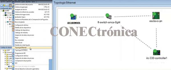
PcWorx can be used to access the network topology.
In the main menu, under "View" >> "Ethernet Topology," the implemented network topology can be viewed, and some diagnostic functions are also available (Figure 15).
1.5. Omron Slave Integration
This section describes the procedure for integrating a Profinet slave from another manufacturer into the network, in this case an OMRON GRT1-PNT.
1.5.1. Name Assignment
Similarly, for the OMRON GRT1-PNT slave, “NetNames” is now used, allowing the correct assignment of a name and IP address to this Profinet device, even though it is from a different manufacturer. This is illustrated in Figure 16.
1.5.2. Integration in PCWorx Software.
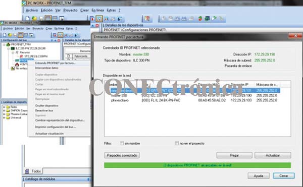
In the project root, under the Profinet section, selecting "Profinet Input by Read" from the pop-up menu will display the Profinet devices, both the master and the Profinet I/O devices. From this window, by selecting the desired I/O device and choosing the "paste" option, you can add the Profinet slave to the project tree. This is illustrated in Figure 17.
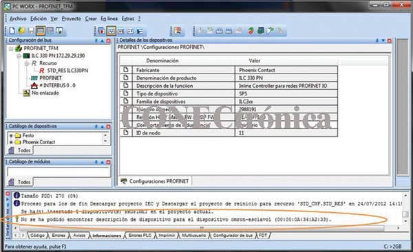
When attempting to connect the OMRON slave, the "Message Window" (Figure 18) will display a message indicating that the device description cannot be found. This means that PcWorx does not yet have the description for this type of Profinet device in its library. Therefore, it is necessary to install it.
1.5.3. GSD Installation in the PcWorx Catalog
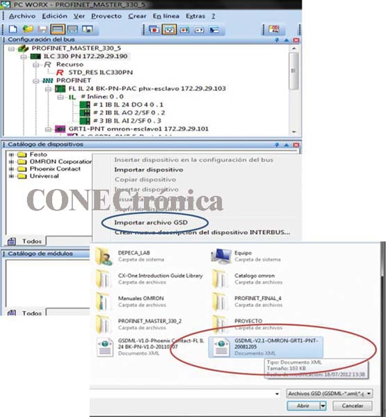
The GSD file containing the description of the OMRON GRT1-PNT device can be downloaded from the official OMRON website. In the "Device Catalog" window, accessible from the "View" tab of the main menu, the "Import GSD File" option appears in the context menu. This option allows you to add the description of the OMRON GRT1-PNT Profinet device to the PcWorx library. This is illustrated in Figure 19.
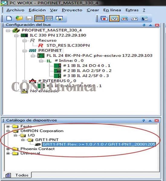
Once the GSD file with the device description is installed, a new OMRON Corporation library appears in the “Device Catalog” (Figure 20) with the device of interest (GRT1-PNT), which can now be added to the Profinet bus.
1.5.4. Integration into the project.
By clicking again on “Entering Profinet by reading” to view the reachable devices on the network, it is possible to successfully “attach” the OMRON Profinet-IO Device to the project bus. In the project tree (Figure 21), the OMRON device can be seen connected to the Profinet bus.

Once the OMRON GRT1_PNT header has been added, the various IO modules connected to that header can be added from the “Module Catalog” window (Figure 22), by dragging and pasting, or simply by double-clicking.
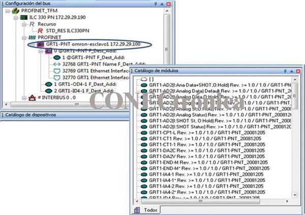
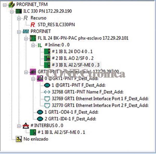
With both the PHOENIX FL IL 24 BK-PN-PAC slave and the OMRON GRT1-PNT slave integrated, the complete configuration of the Profinet network can be seen in the project tree (Figure 23).
By compiling and downloading the project, the address tables will be created (Figure 24), the new configuration will be saved on the master, and the new OMRON GRT1-PNT slave can be authenticated.
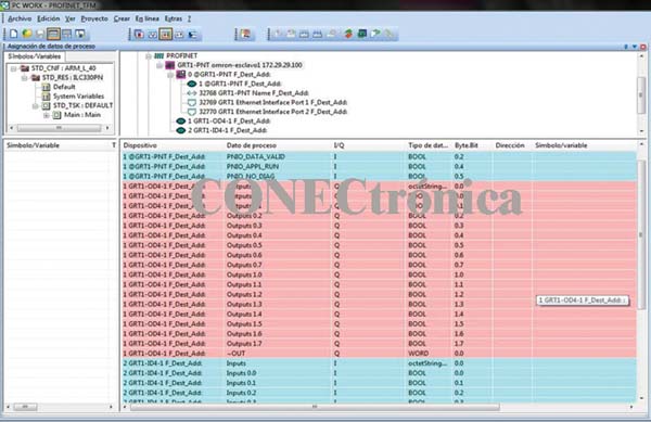
In the data allocation area (Figure 25), all variables representing the devices interconnected by the Profinet network are displayed. Diagnostic records are also included, which allow the connection status of the Profinet I/O communication devices to be determined.
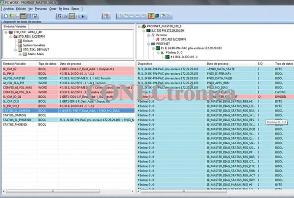
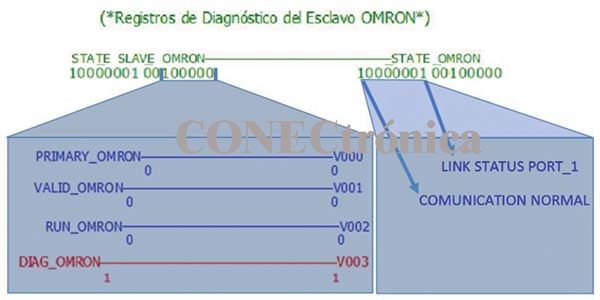
Figure 26 shows the diagnostic records for the OMRON Profinet Slave.
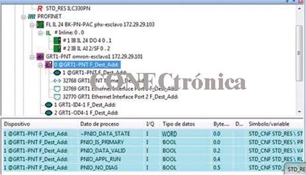
Figure 27 illustrates the "Active Debugging" process. The status of the "Status Log" of the OMRON Profinet Slave indicates that the network configuration and commissioning were successful.
The next article will show the integration of Profinet elements in an Omron environment, using
CX-Programmer and CXConfiguratorFDT.
Author:
Alfredo Gardel, Ignacio Bravo, José Luis Lázaro, Arley Vanegas


