

Their low performance and legacy architecture cannot keep pace with mission-critical systems, which now demand the bandwidth, speed, and flexibility of Ethernet-based fiber optic links.
Fiber optics based on IEEE 802.3 standards offer data rates from 1 Gbps to 400 Gbps, enabling the robust digital infrastructure required by modern avionics. However, this shift presents a challenge: high-speed optical systems are more susceptible to signal degradation from jitter, interference, and attenuation. To maintain signal integrity and achieve the ultra-low bit error rates (BERs) essential for flight and mission safety, designers are turning to a long-established tool in long-haul networks: Forward Error Correction (FEC).
This article explores the principles of FEC, its importance in aerospace fiber optic systems, and the advantages and disadvantages that engineers must consider when implementing it in next-generation architectures.
The growing need for high-speed optical links:
Modern aerospace and defense systems must move ever-increasing volumes of data across harsh environments. Applications such as high-definition sensor data, augmented situational awareness, advanced command and control, and AI-based analytics require high-speed transmission and exceptional signal reliability. This has led to a shift from legacy deterministic systems to high-performance fiber optic links.
IEEE 802.3 Ethernet over Fibre provides a scalable standard for this type of communication, with transmission speeds up to 400 Gbps. While this opens new frontiers in performance, it also introduces greater concerns about signal integrity. Unlike older systems, where lower data rates masked minor losses, high-speed optical links are unforgiving, especially because data encoding methods such as 4-level pulse amplitude modulation (PAM4) reduce voltage margins and increase susceptibility to noise.
In this new context, FEC emerges as an essential tool for achieving reliable communication in noise-prone environments.
Understanding Signal Integrity and the Role of SNR:
Signal integrity in data transmission depends on one critical factor: the signal-to-noise ratio (SNR). Defined as the ratio of signal power to noise power, SNR determines the system's ability to accurately distinguish transmitted information from background interference. It is expressed in decibels (dB) using the formula:
SNR (dB) = 10 · log₁₀ (P_signal / P_noise).
In applications with a high SNR, data errors are infrequent. However, the effective SNR decreases as data rates increase and noise sources accumulate, whether from laser fluctuations, faulty connectors, or receiver limitations. Unless additional measures are taken, a system that performs well at 1 Gbps may experience an unacceptable BER at 25 Gbps.
In the case of critical avionics functions, even a small amount of data corruption can have significant consequences. While some applications can tolerate a BER of 10⁻⁴, security-sensitive systems typically require BERs as low as 10⁻¹². Achieving this performance in high-speed environments requires costly component upgrades or the strategic use of FEC.
From Detection to Correction: How FEC Works
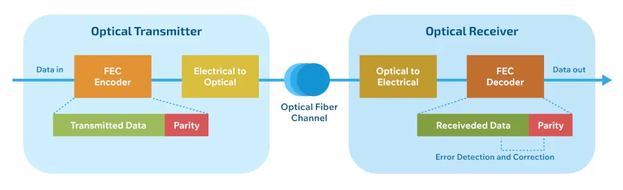
Traditional error management approaches, such as parity bits, checksums, and cyclic redundancy checks (CRCs), can detect errors but not correct them. These techniques are lightweight and fast, but when used alone, they require the system to request a retransmission, which is impractical or impossible in many real-time or one-way communication environments.
FEC solves this problem by adding redundancy directly to the data stream. It adds extra “parity” or “check” bits to each data block, allowing the receiver to detect and correct certain errors without retransmitting them. The most widely used FEC scheme in optical communications is Reed-Solomon (RS) encoding, such as RS(255,239), which encodes 239 data symbols with 16 parity symbols. This configuration allows the receiver to correct up to 8 symbol errors per block.
Therefore, FEC improves the effective BER by orders of magnitude, often from 10⁻⁴ to 10⁻¹². It effectively increases the system's noise tolerance without drastically improving laser power, connector quality, or photodetector performance.
Latency, Overhead, and Design Trade-Offs.
Of course, FEC comes at a cost. Every encoding scheme introduces symbol overhead, increases processing complexity, and adds latency due to block-based encoding and decoding.
For example, RS(255,239) adds approximately 6.3% overhead. Designers can increase the transmission rate to compensate for or accept the reduced throughput. Meanwhile, block processing latency becomes more significant at lower data rates. A 10 Gbps system might have only 1 µs of latency, equivalent to 300 meters of fiber delay, while a 1 Gbps link could incur 10 µs, or 3 kilometers of equivalent delay.
Therefore, engineers must weigh the benefits of improved BER against the added complexity and system delay, especially in latency-sensitive aerospace applications.
Strategic Criteria for FEC Implementation:
Not all fiber optic links in an aircraft or satellite system require FEC. When data rates are low (e.g., 1–2 Gbps), it is often more cost-effective to improve the bit error rate (BER) by upgrading individual link components, such as:
● Increasing laser output power
● Using a diode with a higher extinction ratio (ER)
● Selecting a more sensitive photodetector
● Reducing connector losses.
However, at speeds of 10 Gbps and above, these individual upgrades may not be sufficient. The combined effects of laser jitter, intersymbol interference (ISI), receiver noise, and bandwidth limitations cannot always be mitigated with hardware alone. FEC becomes a strategic necessity to balance the link budget and ensure system robustness under real-world conditions.
Furthermore, FEC implementation requires coordinated changes at both ends of the link—the transmitter and the receiver. While this may increase the initial complexity of the system, it also provides an architectural pathway for scalability and future-proofing, as data requirements continue to grow.
FEC and PAM4: Trading for Reduced Margin.
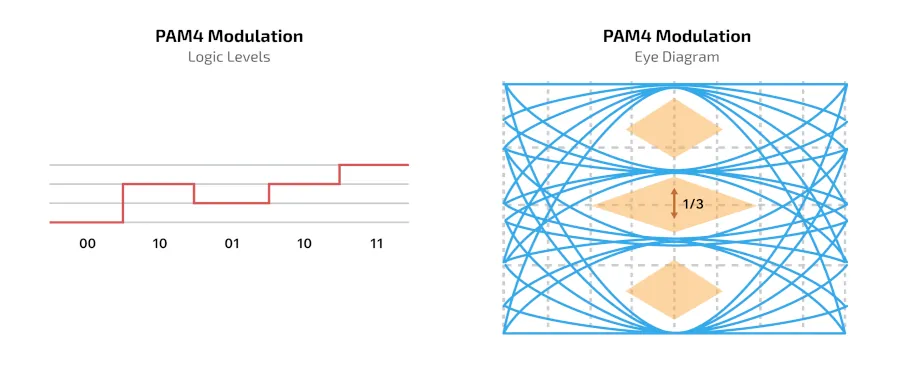
One factor driving the urgency of FEC adoption is the increasing use of PAM4 in high-speed links. PAM4 enables the transmission of two bits per symbol, effectively doubling data rates without increasing the baud rate. However, this comes at a cost: the logic level amplitude is reduced to one-third that of NRZ modulation, degrading the SNR by almost 9.5 dB with a comparable BER.
This reduced margin means that PAM4-based systems are inherently noisier and more prone to errors. Therefore, FEC is indispensable in these contexts. PAM4 systems are often designed with FEC as an integrated feature to enable acceptable BER performance, even under ideal laboratory conditions.
The trade-off is clear: redesigning circuits to reduce noise can be expensive and time-consuming. Conversely, incorporating FEC can be more cost-effective and efficient, especially when using standard components or existing platforms.
System Architecture and Noise Sources in Optical Links
Aerospace systems using optical fiber face several noise sources along the signal path, including:
● Optical Transmitter: Laser modulation jitter and low ER can reduce signal clarity.
● Fiber Cable: Connector losses and modal dispersion can degrade signals, especially in multi-fiber or wavelength-split systems.
● Optical Receiver: PIN diode noise, transimpedance amplifier (TIA) input noise, and sampling jitter contribute to BER.
● Converter Electronics: ISI and bandwidth limitations on both sides of the link further restrict performance.
Collectively, these issues reduce the system's effective SNR. The FEC provides a buffer, improving the BER by 6 to 10 dB depending on the encoding scheme, and allowing systems to meet stringent performance targets without over-engineering each subsystem.
Receiver sensitivity, signal loss, and encoding gain limits:
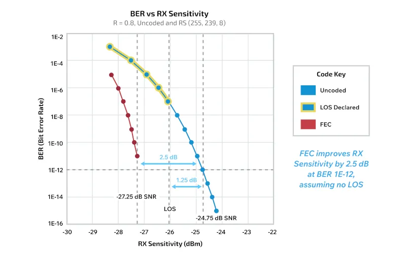
Even in short-range aerospace applications, receiver sensitivity can become the limiting factor. If the receiver declares a loss of signal (LOS) at a threshold higher than the one below which the FEC could still recover the data, the advantage of the FEC is lost.
For example, a system might achieve an unencoded BER of 10⁻⁴ at -24.75 dBm. The FEC could extend the throughput to -26.0 dBm, but if the receiver triggers the LOS at -25 dBm, the additional encoding gain cannot be utilized. Therefore, engineers must design the entire system—transmitter, fiber, receiver, and FEC logic—with consistent performance thresholds in mind.
FEC as a System-Level Enabler
: FEC is no longer a luxury reserved for transcontinental links, but a vital part of high-performance aerospace system design. Whether compensating for PAM4 signal degradation or managing noise on 25 Gbps links, FEC offers increased reliability, lower BER, and greater system resilience.
However, its use requires careful consideration of latency, complexity, and implementation cost trade-offs. The decision to implement FEC should be based on a comprehensive system assessment that considers not only component specifications, but also real-world noise sources and architectural constraints.
Cinch Connectivity Solutions brings decades of experience optimizing high-speed, resilient fiber optic systems for the aerospace and defense industries. With deep expertise in transceiver design and link engineering, Cinch supports mission-critical systems where reliability is non-negotiable. Engineers evaluating FEC strategies for avionics platforms can rely on Cinch's proven capabilities and aerospace approach to design links that will perform under pressure today and in the future.
Author: Grover Brower, General Manager at Cinch Connectivity Solutions -http://www.cinch.com


