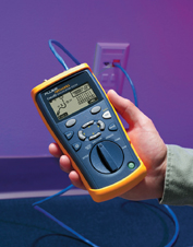
 Will our company's cabling support VoIP or 1GbE? In case of problems, is it easy to identify the socket in the rack? Are the sockets clearly labeled? Can I connect to the network from this wall socket, or is it for telephones? Is the patch cable in good condition?
Security, VoIP, data, and other technologies are increasingly converging on a single connection system: structured cabling and the familiar RJ45 jacks. Meanwhile, traditional analog telephony and video systems continue to hold a significant market share within businesses. Furthermore, data networks are constantly evolving, infrastructure within companies is in constant flux, and therefore maintenance operations are numerous and varied.
Identifying cabling, wall outlets, patch panel connection points, and determining whether a switch port is in use. Checking for network connectivity from the wall outlet, monitoring traffic if needed… these are all small tasks that have long been part of the routine duties of IP network maintenance technicians.
Furthermore, cabling installations and the commissioning of new workstations are increasingly being carried out in operational facilities, making it essential to be as efficient as possible.
This article will showcase various applications and functionalities of different tools and how they can save time and money in maintenance operations.
Identification
is the first task we must undertake. Locate the link we are looking for. Locating means from the wall socket to the connection port on the switch. There are several ways to identify this:
1. Identification in passive sockets (No connection to a switch port).
2. Identification in active sockets (The socket may be connected to an active switch port).
Identification in passive outlets
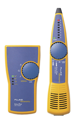
• Tone Generation and Location Technique: This involves generating a signal at the wall jack (on the user's side) and using a tone probe to locate the signal being sent by the tone generator. Two technologies exist: Analog and Digital. Analog technology is useful in telephone installations, but digital technology is preferable in data installations because its operation allows the tone probe to amplify only the digital signal from the tone generator (which is also digital), making the location process faster.
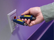
 • Use of Numbered Terminators: Numbered terminators are numbered components that can be identified by specific measuring equipment. This way, if we are in a room with several wall sockets, we can place several terminators with different numbers on the various sockets. The technician would then go to the panel with measuring equipment such as a MicroScanner or CableIQ, and it would indicate whether the connection is to terminator number 1, 4, or 6. This technique, when used correctly, saves a significant amount of time, and therefore money, in the process of identifying the connections to be diagnosed.
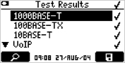
Identification of Active Outlets
• Tone Generation and Location Technique: The same technique can be used, but only if the measuring equipment is capable of generating tones in active outlets; otherwise, it could even be counterproductive.
• Making the Switch Port Light Flash: This is a simple and effective technique, provided the analyzer is designed to communicate with the switch. Those designed for hubs may not work. The method involves instructing the analyzer to make the switch port to which you are connected flash. Once this is done, go to the panel and you will see that among the different ports, there is one whose indicator light is flashing. You will have identified the outlet.
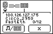
• Communication with the Switch: Recently, devices have appeared that can communicate using the CDP/EDP protocols. In this case, identification is almost instantaneous, since the measuring equipment would indicate the IP address, name, and port of the switch to which it is connected from the outlet (Figure 4).
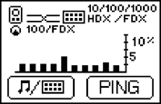
Problem Segmentation: Is it a cabling or application/network problem?
The first step is to rule out cabling issues. This requires using a cable qualifier, a device capable of checking if the cabling supports applications like VoIP, 1Gbps, and 10/100 Mbps.
If the problem lies with the cabling, the source must be identified: incorrect patch cord, impedance mismatch, crosstalk, etc. Ultimately, the cabling should be replaced and certified using an appropriate certifier such as a DTX or DSP.
Cable qualification is a relatively new technique that determines the bandwidth of the cabling, thus revealing whether a cable supports an application like VoIP. These tools are designed for maintaining cabling installations or verifying that existing ones support 1Gbps, VoIP, etc. An example of a cable qualifier is Fluke Networks' CableIQ, which can qualify a cable in just 4 seconds. In other cases, the problem will be more basic, such as a connection issue (split pair) or a continuity problem (shorts, open circuits, reversed pairs, etc.). In these latter cases, an advanced wiring map tester will suffice.
There are different types of testers capable of mapping wiring. In network environments, it is important that the tester meets certain requirements:
- Continuity Map, also called a wiring map. The verifier checks pin-to-pin continuity. This function is necessary but not sufficient, as it is essential to know if the pair-to-pair connection has followed existing standards (568A or 568B).
- Connection Map – Connectorization: This test verifies that the pair-to-pair connections have been made correctly, that is, the pairs (1,2 – 1,2), (3,6 – 3,6), (4,5 – 4,5), and (7,8 – 7,8). A tool that does not check the connectorization should not be considered valid in the world of structured cabling, as it does not guarantee that the patch cords or links are properly connected.
- Distance to Fault (TDR): This technique allows, in case of short circuits or open circuits, the indication of the distance to the fault, saving time and money. It also allows for inventorying installations by indicating the distance of the links.
If the problem is not the cabling, you need to check the network connection configuration:
- Is the switch port configured for 10/100/1000?
- With what transmission type: Half Duplex/Full Duplex?
- I have connectivity to critical devices such as DHCP servers, DNS servers, routers, etc.
- Is it a traffic, broadcast, or other issue?
- In the case of VoIP or security, it's also important to know if the wall outlet has PoE, as this provides better visibility and helps prevent problems with active network equipment or PCs.
- If I have VoIP terminals: are the quality parameters adequate? If they aren't, and the cable is fine, I may need to escalate the issue to another department.
- Finally, if the problem is indeed with the cabling, it's crucial that the company installing the cabling certifies it according to existing standards. Below are some of the basic requirements for a cable certification tool to be used in active installations:
1. Comply with Level III (Category 6, Class E).
2. Be accredited by UL or another independent body, and the installer must include the accuracy charts from the relevant body. A letter of approval is not sufficient; the charts are required. This is the only way to guarantee that the measuring equipment is suitable.
3. Expert fault diagnosis. (In active environments, this is essential, as users will experience significant inconvenience if the exact location of problems is unknown. This will increase the time it takes to resolve the issue, generate user complaints, and therefore raise costs. An expert diagnosis consists of:)
- Impedance problem analysis (HDTDR technique). - Crosstalk problem analysis (HDTDX technique). - Fault interpretation with corrective action suggestions (Example: FAULT INFO function of the DTX-1800 ( Fluke Networks Category 6A/10GB equipment )). 4. Channel and Permanent Link measurement. 5. Be certified by at least 30 Cat 6 cabling manufacturers. 6. Use a centered/reference connector for Permanent Link measurement.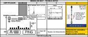
Furthermore, it is important that the installer or certification technician is trained to perform measurements. This requires that they have completed certification courses, such as the CCTT, which certifies that the technician knows how to perform and interpret the results.
Figure 7 illustrates different types of fault diagnoses.
Team differentiation
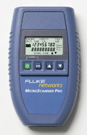 1. Cable Testers:
Equipment that checks the wiring map and optionally the connection/connectorization. They are used for basic cable checks and can indicate distance to fault and open circuits (if they have TDR technology). Example: MicroScanner PRO.
2. Qualifiers:
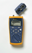 Maintenance equipment that measures cabling bandwidth and whether it supports applications such as VoIP, 1Gbps, etc. It can indicate distance to continuity failure, impedance, and crosstalk. It can also detect unused wall outlets.
Example: CableIQ
3. Connectivity Testers:
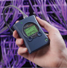
They allow you to know if the wall socket is active, perform connectivity checks, ping, and identify wall sockets (telephony, data).
Examples: LinkRunner, NetTool
4. Certifiers
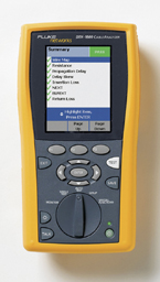 guarantee the current and future cabling infrastructure and ensure it complies with cabling standards such as ISO-11801 or TIA-568B. They check attenuation, crosstalk, RL, propagation time, ELFEXT, etc.
Examples: DTX-1800 or DSP-4000PL.
Author:
Nicolás Bravo de Medina. Telecommunications Engineer. Fluke Networks.