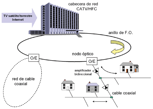
Modern HFC telecommunications networks must be prepared to offer a wide range of applications and services to their subscribers. Most of these services require the network to establish bidirectional communication between the headend and subscriber terminal equipment, and therefore need an uplink or return communication channel. As an example, Figure 1 shows the infrastructure of a bidirectional HFC network. Optical nodes are responsible for converting the optical signal to an electrical signal for the downlink and vice versa for the return link, thus requiring an optical transmitter. The return channel in HFC networks occupies the lower part of the spectrum. This bandwidth is shared by all households served by the same optical node. Return signals from different nodes reach the headend via different paths or multiplexed at different wavelengths. In this way, a signal generated by a subscriber's terminal equipment travels up the coaxial distribution network, passing through bidirectional amplifiers until it reaches the optical node. Here the return signals from all subscribers converge, which are converted into optical signals by means of the return laser and transmitted to the headend.
 In order to be able to use the same receivers as those used with terrestrial TV, cable networks use the same frequency band for the downlink, although HFC systems expand this band up to 862 MHz or even 1 GHz, leaving the lower part of the spectrum (5-42 MHz in the United States and 5-65 MHz in Europe) as a return channel for commands, because this region is more subject to interference. A large number of analog TV channels can be included in the usable bandwidth, considering that with the American NTSC standard, a TV channel occupies a bandwidth of 6 MHz, while with the European PAL or SECAM standards, this increases to only 7/8 MHz. In the case of digital signals, a 6 MHz RF channel can provide a data flow of 27 Mbit/s from the network headend to the end user using 64QAM transmission techniques, or even higher (up to 38 Mbit/s) if 256QAM is used. In the reverse direction, from the user to the network headend, simpler modulations such as QPSK are used, which provides a speed between 256 kbit/s and 5 Mbit/s and does not require sophisticated equipment in the user's home. Alternatively, DPSK can also be used, which is somewhat slower but offers greater immunity to interference.
Cable modems: DOCSIS standards
Access to the internet at ever-increasing speeds is one of the major business opportunities for new broadband access networks. HFC networks, using modems specifically designed for digital communications over cable networks, can offer data network access services like the internet at speeds far exceeding those achievable via ADSL. In fact, cable modems have transformed CATV/HFC networks into true providers of video, voice, and data telecommunications services.
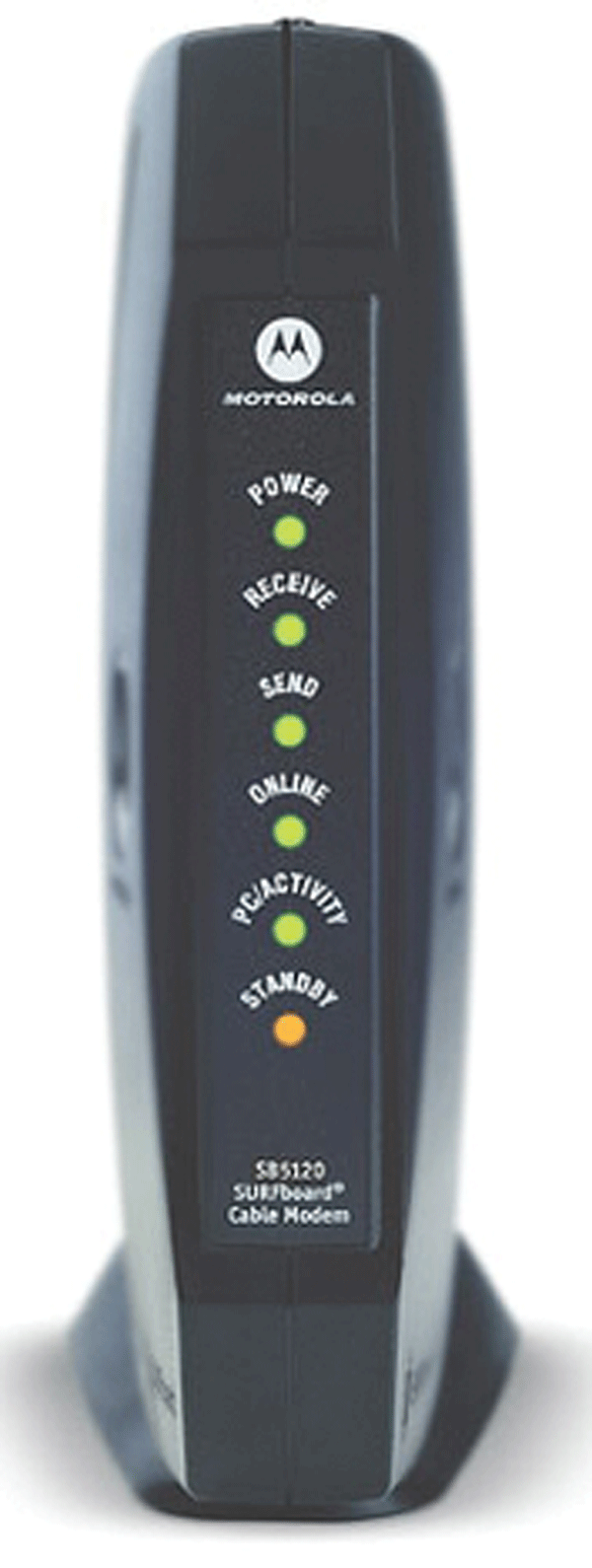 A typical cable modem is characterized by its asymmetric nature: it receives data at speeds of up to 30 Mbit/s and can transmit at up to 10 Mbit/s. It connects to the HFC network via an F-type coaxial cable connector and to the subscriber's PC via an Ethernet card. Data reception occurs through a 6-8 MHz channel in the 606-862 MHz band, typically using 64QAM digital modulation. The cable modem demodulates the received signal and encapsulates the bitstream into Ethernet packets. This allows the subscriber to perceive the HFC network as a single, large LAN. Upstream, the cable modem decomposes the Ethernet packets received from the PC and converts them into ATM cells or proprietary frames. Subsequently, using a 2 MHz channel in the return spectrum, the data is transmitted to the headend using QPSK modulation. Figure 2 shows an example of a cable modem.
The standards applicable to these types of modems have evolved over time, although today the vast majority are based on the DOCSIS standard. Data Over Cable Service Interface Specification (DOCSIS) is an international standard developed by CableLabs with contributions from a number of companies, including ARRIS, Broadcom, Cisco, Conexant, Correlant, Intel, Motorola, Netgear, Terayon, and Texas Instruments. Specifically, it defines the cable modem interface requirements for use in cable data distribution systems, that is, digital services over CATV/HFC networks. Thus, DOCSIS enables high-speed data transfer using the RF channels of the CATV system, allowing CATV operators to offer Internet access through their existing HFC infrastructure.
 The first DOCSIS specification (version 1.0) was published in March 1997, along with a subsequent revision 1.1 in April 1999. However, due to the increasing demand for real-time symmetrical services, such as VoIP (Voice over IP), DOCSIS was revised again to improve uplink transmission rates and incorporate QoS capabilities. This revision (DOCSIS 2.0) was released in January 2002. The International Telecommunication Union (ITU) adopted both versions as international standards: DOCSIS 1.1 in its ITU-T Recommendation J.112 and DOCSIS 2.0 in its Recommendation J.122. Finally, the DOCSIS 3.0 specification has recently been published, which includes several improvements such as increased channel capacity, enhanced network security, expansion of the IPv6 address space, and the deployment of new service offerings.
Because the frequency plans of CATV systems in Europe and the United States differ, the DOCSIS standards were modified for use in Europe. These modifications were published under the name EuroDOCSIS. The main differences relate to the bandwidth of the TV channels: European cable channels conform to the PAL TV standard with a bandwidth of 8 MHz, while in North America, NTSC channels have a bandwidth of 6 MHz. This greater bandwidth of EuroDOCSIS architectures allows for a higher data capacity in the downlink links. Similarly, other variants of DOCSIS are also used in Japan.
In subsequent articles, we will present the specifications and requirements of the DOCSIS standard in greater detail, as well as the tests performed on HFC systems and networks based on this standard.
Test instrumentation
 Among the most typical measures to be carried out in these networks are: signal loss, system sweep, monitoring of analog and digital video channels, DOCSIS service testing, VoIP, maintenance of forward and return paths, etc.
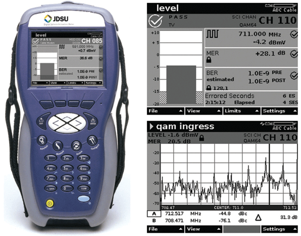
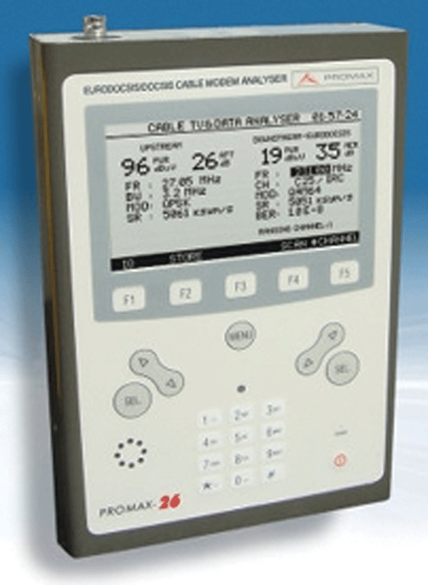
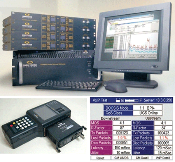
As an example, some of the commercially available equipment is described below. JDSU offers a specific line of instruments for testing HFC networks. Figure 3 shows the DSAM-6000, an example. This is a sweep multimeter for measuring the quality of analog and digital video channels, as well as DOCSIS and VoIP (PacketCable) carriers. It covers a frequency range from 4 to 1000 MHz, analyzing both the downlink and return channels. Its capabilities include: signal level measurements (CNR, tilt), full band monitoring (up to 999 channels), constellation diagrams for digital modulations, BER, MER (modulation error rate), ES (seconds with errors), SES (seconds with many errors), etc. PROMAX is also a notable company with a line of telecommunications network testing products. Regarding cable TV, it offers a full range of equipment for monitoring cable channels and digital modulation. Among these, the PROMAX-26 (Figure 4) stands out. This DOCSIS and EuroDOCSIS transmission system analyzer is designed for the installation and maintenance of high-speed interactive video, voice, and data services over CATV networks. It includes an Acquisition (LOGGER) function, which allows for the recording and storage of measurements for later review, transfer to a PC, or printing. It also allows for the monitoring of quality parameters very similar to those previously mentioned. Finally, Sunrise Telecom should also be mentioned as a provider of broadband CATV network testing solutions. It offers a wide range of testing solutions, including VoIP and DOCSIS capabilities. Figure 4 shows an example of this equipment.
 The distribution of "triple-play" services (voice, video, and data) over HFC networks requires the selection and use of appropriate testing applications and equipment. Multiple testing solutions are available on the market, covering everything from the network headend to remote nodes and even customer equipment. Regarding the fiber optic section, equipment such as OTDRs and optical spectrum analyzers have already been presented in previous articles. However, CATV/HFC networks require additional equipment for troubleshooting network activation, certification, service testing, maintenance, and monitoring.