The capabilities of PTP could change how we handle many common testing requirements in the future. This article describes how it works and how we can benefit from this technology. PTP precisely synchronizes the real-time clocks embedded in many modern system components. Like the Network Timing Protocol (NTP), PTP operates over Ethernet and TCP/IP. However, it is much more precise: synchronization down to 100 ns or even better can easily be achieved. You might think such systems would be fragile and difficult to configure, but they are not. As we'll see below, system setup is easy and mostly automatic. But first, let's look at some basic IEEE 1588 concepts.
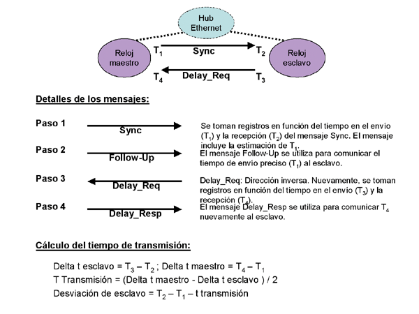 PTP is based on a master-slave architecture. Slave clocks are synchronized with the master clock (typically the one with the most stable and accurate time base). The key to PTP's accuracy is how it accounts for message transmission time across the LAN when evaluating slave clock deviation (see Figure 1).
As shown, the master clock sends a synchronization message, "Sync," to the slave at regular intervals. The slave responds with a delay request message, "Delay_Req." Both the sending and receiving of these messages are time-logged by the clocks. The four resulting time-logged records are then used to calculate transmission time (the time the message is actually being transmitted at the physical network layer). Note that the calculation shown in Figure 1 is based on the assumption that transmission time is symmetric (with Ethernet, this is a perfectly reasonable assumption). With the transmission time and the registers based on the Sync message time, calculating the slave clock deviation is straightforward.
Hardware is better than software.
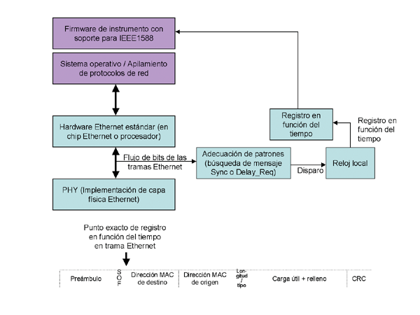
Although not a strict requirement, for optimal performance, timing registers are taken in hardware, at the physical network layer. Why? The key to perfect synchronization is stable and repeatable timing registers with minimal variation. And the best way to achieve this is through hardware design (see the conceptual block diagram in Figure 2).
With an Ethernet design featuring a separate physical chip (physical layer implementation), it is relatively easy to capture the bitstream of Ethernet frames. Pattern-matching hardware will then look for an incoming Delay_Req or outgoing Sync message pattern. Note that the IEEE 1588 standard specification clearly indicates which bit transition timing registers should be captured.
In the design described above, the timing register is captured as if the Ethernet frame were actually being sent out to the physical network layer. Therefore, the timing register cannot be sent as part of the same message. The Follow-Up message (see Figure 1) is used to communicate the time-based log ("precise sending time") separately from the original Sync message.
In some situations, it may be sufficient and perfectly reasonable to use a software application to take the time-based log. However, the resulting synchronization accuracy will be, at a minimum, much lower due to the timing jitter associated with network protocol stacking software.
Network delay jitter is the enemy.
As mentioned earlier, the clock correction algorithm relies on the assumption of symmetrical transmission times. Therefore, fluctuations in transmission times (one-way) will degrade synchronization accuracy. For optimal performance, choose a network infrastructure with minimal delay jitter.
 An Ethernet hub will exhibit relatively low and stable latency by design. A hub is a simple signal repeater, and Ethernet frames are neither stored nor interpreted in any way. An Ethernet switch will exhibit higher latency and, more importantly, much higher jitter. The switch analyzes incoming frames and queues them for output on the appropriate destination port. A router exhibits an even higher level of jitter because it inspects packets at the IP layer and stores and forwards them using software mechanisms.
If you want to use a switch or router for their additional capabilities at network layers 2 or 3, respectively, you don't need to tolerate their higher jitter and the resulting reduction in synchronization accuracy. Point-to-point (PTP) uses a mechanism called a peripheral clock to neutralize the negative effect of network elements that exhibit high jitter (see Figure 3).
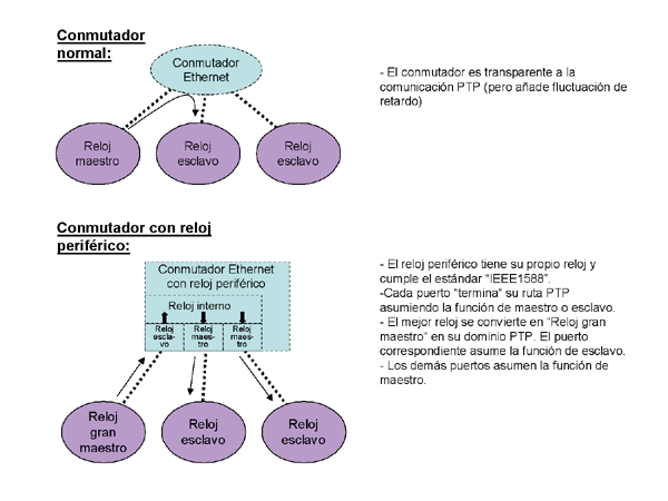 A peripheral clock is a switch or router that has its own built-in real-time clock and complies with the IEEE 1588 standard. Except for PTP timing messages like Sync and Delay_Req, it behaves like a normal switch or router. However, with respect to PTP, the peripheral clock terminates the "synchronization path" behind each individual port. The port connected to the best clock (grandmaster clock) acts as a slave clock. Consequently, the internal clock in the switch or router synchronizes with the grandmaster clock through this port. The other ports act as master clocks. As a result, all slave clocks in their respective synchronization path synchronize with the peripheral clock's internal clock.
The peripheral clock mechanism dramatically increases synchronization accuracy (to the level of a simple Ethernet hub or even better) because the IEEE 1588 timing messages are not switched or routed through the network element (unlike other IP packets or Ethernet frames). Consequently, a significant source of delay jitter (store and process in the network element) is eliminated from the equation.
How far can this go?
As we have seen, a system designed for maximum performance should adhere to two important rules. First, it should use a hardware-assisted implementation of the IEEE 1588 standard for the master and slave clocks. Second, it should use an appropriate network infrastructure: a simple Ethernet hub or a more complex network element (switch or router) with a peripheral clock. If we follow these rules, how high can we go in terms of synchronization accuracy?
With hardware-assisted techniques, accuracy is limited by two factors: the clock capture of the physical implementation and the stability of the oscillator or local clock itself. When implementing Fast Ethernet, clock capture jitter is typically in the low range of less than ten nanoseconds. The effect of this jitter can be reduced quite effectively using statistical methods. The variation of the local oscillator depends heavily on the system design and could easily minimize clock capture problems. It should be noted that the Sync message interval can be reduced to 1 s, but not less. A design with high stability would need to exhibit limited variation to accommodate the stability of the clock capture (small ns range). This might require a relatively expensive solution based on a thermally resistant oscillator.
The best designs will include appropriate statistical methods to reduce the effect of delay fluctuation. The IEEE 1588 standard does not specify the use of an averaging algorithm; therefore, this is another area where manufacturers can make a unique contribution to their solutions.
Are these systems difficult to install?
One of the most interesting aspects of the IEEE 1588 standard is that system configuration is mostly automatic (unless you prefer to control the configuration process). Let's see how this is possible.
Each clock maintains certain sets of data that describe its inherent capabilities (e.g., its stability) and its actual configuration (e.g., an estimate of the real-time deviation from the master, as well as the master clock's identification). These (and other) parameters describe a clock's quality and are "published" as part of every Sync message sent by the clock.
When a clock comes online, it assumes the master role and begins sending Sync messages (containing its specifications). Other clocks receive the quality parameters and compare them to their own specifications (using the "Best Master Clock" algorithm). If they perceive a better master clock, they assume the slave role.
What are the criteria for a "good" clock? One important parameter is the "clock stratum." This value indicates whether the clock has direct or indirect traceability to an "official" standard time source, such as a GPS receiver. Clocks with a direct link to such an absolute time source are preferred. Another important parameter is "clock variance," an indication of the clock's inherent stability.
As mentioned earlier, the automatic or default settings can be modified if desired. The IEEE 1588 standard also defines several management messages for this purpose. These allow you to query the clock's data sets, adjust the real-time setting, and change the clock's status or other operating parameters over the LAN.
So, what is this technology used for?
Data acquisition is an obvious application of the IEEE 1588 standard. Many data acquisition applications require sensors to be distributed across a large area (for example, in industrial facilities or wired/wireless communications). But even in centralized applications, it is necessary to synchronize different instruments or data acquisition units. In all but the most trivial applications, it is crucial to know when individual measurements were taken. The high timing accuracy offered by IEEE 1588 opens up more possibilities for post-processing and analysis, which in turn allows for better understanding. Without IEEE 1588, it would be necessary to synchronize instruments using separate GPS receivers or a centrally generated trigger signal for synchronization. The first option is expensive, and the second is not straightforward due to propagation delay and trigger jitter noise.
Functional testing is another area that will greatly benefit from IEEE 1588. It is often necessary to apply stimuli in a predefined sequence and with precise timing. It is also necessary to measure or record the reaction of a device under test (DUT) at a predefined point in time. Even the most complex scenarios are easy to implement using the time-based triggering enabled by the IEEE 1588 standard. Without it, it may be necessary to generate one or more hardware trigger signals and route them to the various instruments in an appropriate manner. Time-based triggering provides much greater flexibility because it is not limited by physical cabling and does not experience signal quality issues.
Summary:
The IEEE 1588 standard is a fascinating technology. If you work in systems applications, you should definitely consider it. This technology and its features could make your life easier. Point-to-Point (PTP) enables system-wide time-based logging and precise time-based triggering without the need for complex wiring. Therefore, it offers an unprecedented level of flexibility in this area.
The author,
Stefan Kopp, holds a degree in Computer Science from the Stuttgart University of Cooperative Education in Germany. He has worked with Agilent (formerly HP) since 1989 in various roles, including project manager for custom testing solutions and sales representative. His current position is consultant in the area of test automation and test system components.