 Once an optical link has been installed, it is necessary to take the measurements required to verify its proper installation. The technician must ensure that the results obtained—in terms of attenuation and return loss, if applicable—correspond to the project requirements; that is, with the loss balance or the expected permissible losses.
For this purpose, there are two types of measuring equipment available: optical power meters and optical time-domain reflectometers (OTDRs). Which one should be used? What are the basic differences between them? Are they both equally accurate and reliable? Furthermore, is it necessary to measure each fiber in both directions? At what wavelength should the measurements be taken?
This article will attempt to answer these questions.
Optical power measurement equipment: (OLTs)
An OLT (Optical Loss Test Set) consists of several elements:
- A stable light source capable of emitting at the wavelengths (λ) specified in the installation (850 and 1300 nm for MM fibers; 1310, 1550, and 1490 nm for SM fibers).
- A power meter capable of detecting the wavelength (λ) emitted by the source, calibrated for the wavelengths specified in the project. The source's emission power and the meter's sensitivity must be sufficient to overcome the expected loss range.
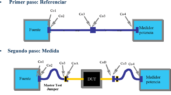
- A set of accessories (measurement cables, matching devices, cleaning tools, etc.) that allow for the basic operation of the diagram in Figure 1.
Consequently, the recorded losses will correspond exactly to the actual losses of the circuit being measured, without any additional information.
To accurately reproduce all the circuit's operating possibilities, power measurements must be bidirectional and at all wavelengths intended for transmission.
Depending on the equipment's characteristics (automatic data logging capability, computer connection, automatic wavelength recognition, the number of wavelengths for which the meter is calibrated or which the source emits, threshold setting capabilities, etc.), OLTS devices will be faster or slower in operation and report generation. Access to both ends of the fiber is required.
Optical Time-Distance Reflectometers (OTDRs)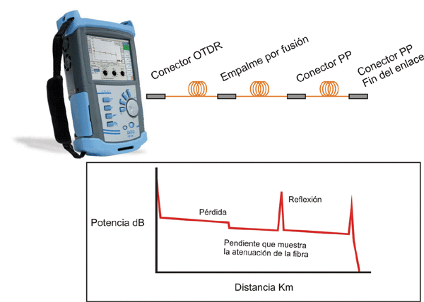 OTDRs emit a pulsed light signal from one end into the fiber being measured, which travels along its length. The device then collects and analyzes the portions of this signal that have been reflected back due to Fresnel and Rayleigh reflections (backscattering). The result is an Attenuation/Distance graph that reflects all events, both reflective (connectors, fiber splices) and attenuating (bends, splices). See Figure 2.
The reflectometric graph provides all the precise information about incidents along the cable, making it an indispensable tool for locating events (bends, connectors, splices, etc.) due to the accuracy of the measurement. In this case, bidirectional measurements must also be carried out, and in different l, since, in addition to the reasons pointed out for OLTS, it will allow us to identify a certain type of OTDR. The suitability of its characteristics (dynamic range, attenuation dead zones and events, working l) to the measurement needs.
Conclusion: OTDRs or OLTS?
As we discussed earlier, each type of instrument provides highly accurate and valid measurements, once its specific characteristics are understood. However, in general, power measurements with OLTS will be sufficient for short links with few events (LAN links, for example), while OTDR graphs will be accurate for long-distance links with multiple events (WANs, telecom links).
Nevertheless, it will always be necessary to perform bidirectional measurements at multiple wavelengths (those planned for operation, plus 1625 nm, if our equipment allows it).
Miguel Ángel Matesanz, Technical Director of C3comunicaciones