In this environment and circumstances, the design, management and administration of the data center's fiber optic information transport infrastructure become fundamental.
The choice of network topology, the definition of its physical structure, and the choice of the materials that make it up must take into account the reliability, simplicity, and useful life that is intended to be achieved.
 In this regard, the incorporation of 40 and 100 GHz channels in data centers requires links comprised of parallel multi-fiber structures, very different from those needed for duplex channels.
However, reality demands that both types of links can be established simultaneously in a data center, and switching between them should not disrupt network management and performance.
'
Duplex Connectivity (Base 2)
Before explaining what parallel multi-fiber connectivity is, it's helpful to remember how a duplex link works.
The purpose of the two fibers in a duplex link used to establish a simple bidirectional telecommunications channel is for each fiber to carry the signal from a transmitter (Tx), located at one end, to a receiver (Rx), at the opposite end.
 The correct arrangement of the fibers to achieve this, regardless of the number of connectors managed in the link, is called Base 2 polarity.
To understand its importance, let's analyze what happens if, when trying to establish a duplex channel, it is found that the signal that should be delivered to the receiver (Rx) is coming out of the connector intended for the transmitter (Tx).
The simplest solution is to swap the two single-pole connectors at the same point in the link, at either end or at any intermediate management point.
It's easy to deduce that this solution can lead to a bigger problem than the one it intends to solve: the loss of control of the physical network as a consequence of a loss of confidence in network management, due to the enormous number of connectors in a data center.
However, even without reaching such extremes, we can encounter more immediate difficulties in applying the simple solution because:
- there is not enough time to test the correct polarity on each piece of equipment or port that is connected (a common situation in data centers).
- duplex connectors do not allow for the interchange of individual connectors.
- different types of connectivity with different polarity bases (Base 2, Base 12, Base 24, etc.) coexist on the network, preventing proper operation without correct planning and management.
To avoid this situation, the basic management principle of a network based on Base 2 polarity channels is based on the AB Rule.
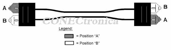
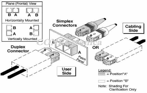
 This rule states that when two fibers have duplex connectors at both ends, the fiber that occupies position A of the connector at one end must occupy position B at the opposite end, so that if the ends are swapped, the resulting arrangement must be similar.
This rule applies to both duplex patch cords and cable glands, as well as to trunk lines.
For patch cords, the rule is easy to follow if the connectors at both ends are duplex. Figure 1 shows their arrangement. Regarding
duplex cable glands, it is easy to verify that the AB marking is swapped on both sides, so they always comply with the rule (for this reason, many manufacturers no longer mark their duplex cable glands with A and B). The generalization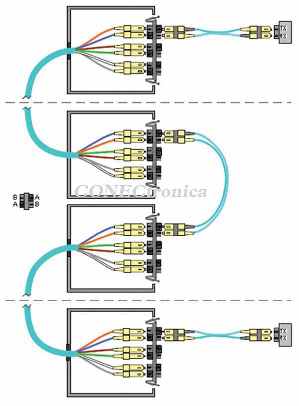 of this rule to trunk lines, typically formed by an even number of fibers greater than two, is called the Reversed Pair Rule.
This rule should only be applied when duplex cable glands are available at both ends, since Base2 polarity does not apply to links with single-ended cable glands at one or both ends.
The reversed pair rule consists of reversing the order of the fiber pairs at both ends.
Following this criterion, Base2 polarity is maintained regardless of the type of duplex connector, the type of components used, and the number of interconnections established in the link to create a communication channel.
'
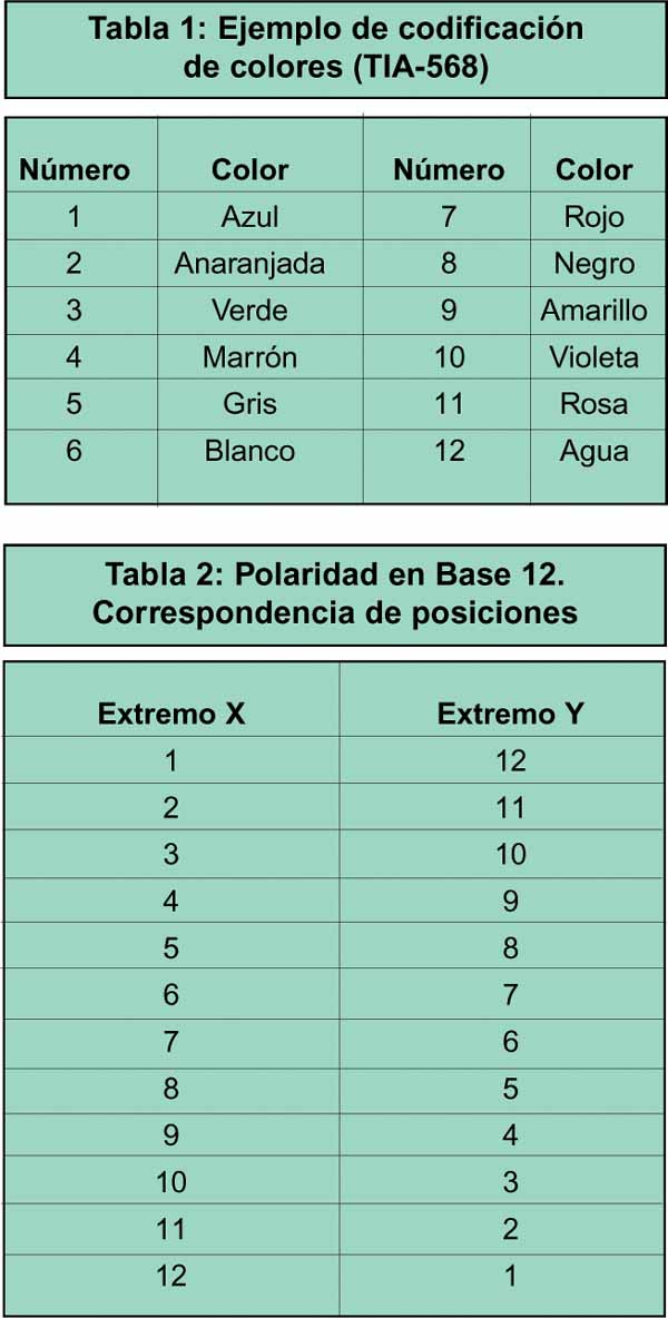
To implement the reversed pair rule in practice, proceed as follows: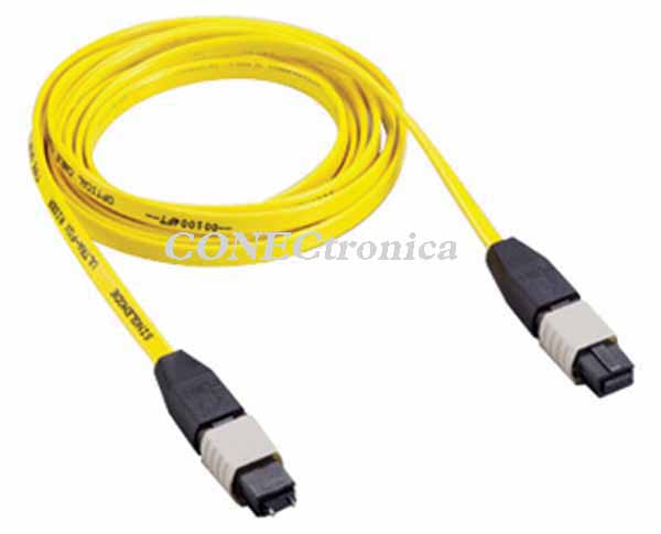 1. Assign each fiber in the cable a sequential number (since each fiber corresponds to a color, it is recommended to follow a standard color coding). See example in Table 1.
2. Verify that the duplex cable glands are positioned identically at both ends. Figure 2a
. If they are in a horizontal position, the connector's "key guide" is usually placed at the
top.
b. If they are in a vertical position, confirm that the "key guide" is
on the same side (right or left) at both ends.
c. If the cable glands are not arranged the same way at both ends, assign correspondences
between the cable glands at both ends.
3. Install the connectors in the duplex cable glands at both ends according to the following criteria:
a. At one end of the cable, install the connectors in the cable glands in consecutive order (1-2, 3-4, 5-6
…) e.g. From left to right (or from top to bottom).
b. At the other end of the cable, install the connectors in the cable glands in reverse pair numbering (2-1, 4-3, 6-5…), in the same direction as at the other end: e.g., from left to right (or from top to bottom).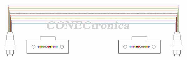 Special care must be taken when applying step 3 in case 2.c, as it is very easy to make a mistake. The main cause of error stems from the fact that, if present, alternating AB markings on both sides of the same duplex cable gland can lead to errors when correctly positioning the
 trunk fibers.
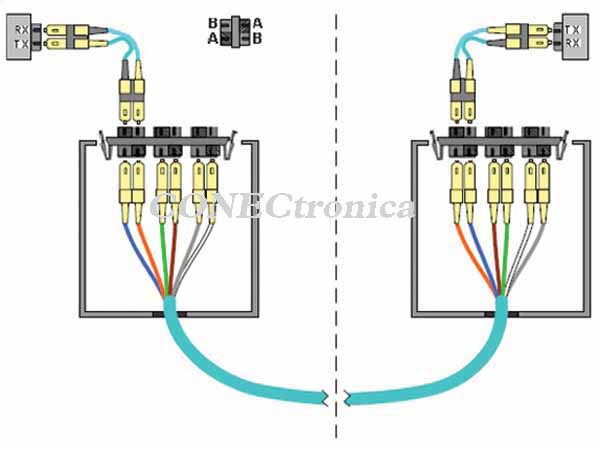
One way to understand the coherence of Base 2 polarity is to see that the sum of the components needed to establish a channel (trunks + bulkheads + patch cords) is always an odd number.
Indeed, the fewest 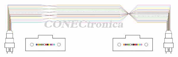 number of elements required to establish a channel is one patch cord. If two patch cords are joined to create the channel, a duplex cable gland is needed to connect them, so the number of elements becomes three. Following this pattern, whether adding trunk lines or patch cords to the channel, the same number of cable glands is always added, so the final number of elements that make up a channel is an odd number. See examples in Figures 3 and 4.
 Parallel Multifiber Connectivity (Base 12)
As previously mentioned, the incorporation of 40 and 100 Gbps transmission systems in data centers has necessitated a rethinking of connectivity in these environments.
To transmit such high data rates, there are essentially two approaches.
The first involves developing transmitters and receivers with sufficient bandwidth to manage this enormous amount of data. This option encounters physical limitations inherent to the internal dynamics of optoelectronic devices, which is hindering its implementation in commercial products.
As an alternative, the second approach is based on decomposing the high-rate channel into several lower-rate “sub-channels” and then aggregating them. In this case, the transmission rate chosen for each sub-channel is, at most, 10 Gbps, for which commercially available optoelectronics are available.
Several options are being considered for transporting these sub-channels, ranging from wavelength multiplexing over a single fiber to parallel transmission over independent fibers, as well as phase and polarization multiplexing.
Of all these options, parallel transmission over independent fibers is the easiest to implement and is by far the most economical when the channel length is short, as in the case of a data center.
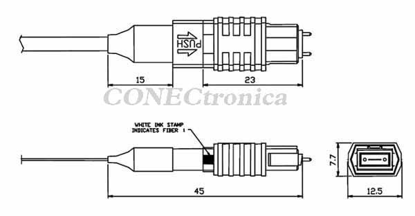
To implement this solution, the fibers are grouped together under a single connector. The most popular connectivity solution using this approach is based on the MPO connector. See Figure 5.
The most common configuration in an MPO connector is a single row of 12 fibers. It's clear that this large number of fibers allows for a wide variety of combinations when assigning positions to the connectors at the ends of a patch cord or trunk cable.
Of all the possible configurations, one has been standardized that is capable of guaranteeing communication based on the aggregation of sub-channels in parallel. This arrangement is called Base 12 polarity. See Table 2.
'
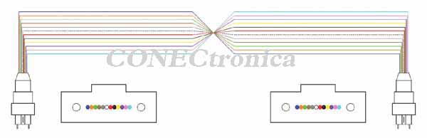
To implement this polarity base, the arrangement of the connectors of a trunk or patch cord must follow the Key-Up / Key-Up Rule. See Figure 6.
Key-up/Key-down configurations, both direct and inverted pairs, follow a philosophy based on the same criteria applied when establishing classic links with single-ended or duplex (AB) connectors, respectively. It is easy to see that they do not comply with Base-12 polarity, since they assign position 1 at one end to position 1 at the other (direct case, Figure 7a) or alternate even and odd positions two by two (inverted pair case, Figure 7b).
With Base-12 polarity (Key-up/Key-up), communications using several parallel sub-channels, such as 40 and 100 G, are easily implemented, as can be seen in the diagrams shown in Tables 3 and 4. However, it is impossible to establish this type of channel with Key-up/Key-down configurations, as already explained.
 Note that to manage 10 sub-channels in each transmission direction, two 12-fiber sub-links are required per channel. In this case, the two sub-links must be arranged to connect the Tx and Rx ports at both ends. This arrangement is equivalent to combining a Base2 polarity at the sub-link level with a Base12 polarity at the fiber level. This combination of polarities is known as Base24 polarity.
There are several ways to achieve Base24 polarity, but all of them are dependent on the type of connector used. Thus, if 24-fiber MPO connectors are used in a two-row arrangement of 12 fibers, the sub-link formed by the fibers in the lower row at one end must correspond to those in the upper row at the opposite end.
However, the most common practice is to use 12-fiber MPO connectors. In this case, the MPO female connectors are arranged in pairs, and the management of sub-links is similar to how fiber optic links are managed when using individual connectors. That is, it's similar to managing duplex channels with individual patch cords, except that in this case, each patch cord consists of a group of 12 fibers.
There is one final consideration regarding MPO connectors that should be taken into account because, although it doesn't directly affect polarity, it influences network design and the selection of its components.
Since the fibers are arranged in a single block, it's not possible to control fiber alignment at the connections using a sleeve in the bulkhead. To achieve precise fiber alignment, a key and keyway solution is used. The key (also called a bolt, pin, etc.) fits snugly into the keyway or hole, preventing lateral movement of both connectors.
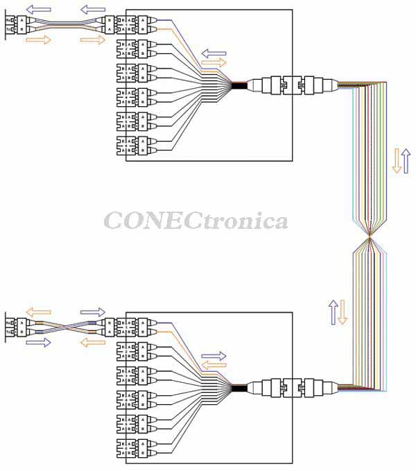 Method A (Single-configuration trunk):
1) Two different types of duplex patch cords.
2) Simple key-up/key-down trunk configuration.
Incompatible with 40/100 G.
3) Allows the use of a single configuration on all adapter modules.
'
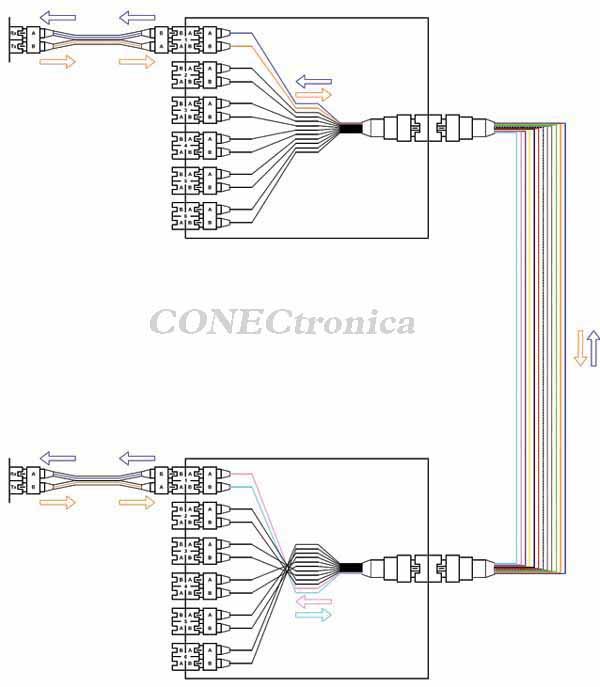 Method B (Parallel Trunk):
1) A single type of duplex patch cord conforming to rule AB.
2) Parallel key-up/key-up trunk.
Compatible with 40/100 G.
3) The responsibility for the correct Base2 to Base12 adaptation lies exclusively with the adapter modules. Some options require different configurations at both ends.
'
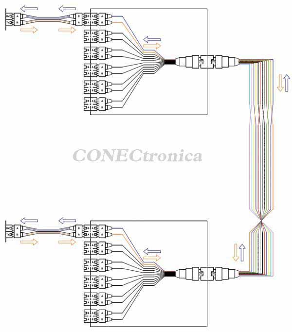 Method C (Duplex Trunk):
1) A single type of duplex patch cord conforming to rule AB.
2) Duplex key-up/key-down trunk (applies the reversed pair rule to a single configuration).
Incompatible with 40/100 G.
3) Allows the use of a single configuration on all adapter modules.
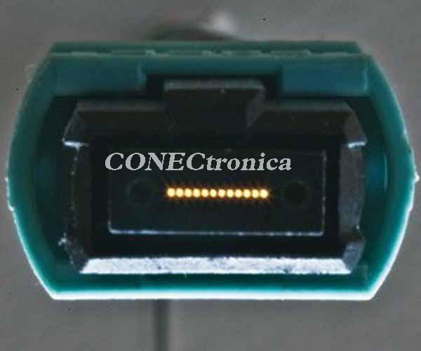
The design chosen for MPO connectors determines that they have either two keys (male MPO connectors) or two keyways (female MPO connectors). Therefore, in MPO connectors, the "female" designation can no longer be associated with cable glands, as is the case with "classic" connectors. See Figures 8 and 9.
Industry standards could have defined MPO connectors with one key on one side and one keyway on the other. With this arrangement, all connectors would have been identical, but this option entails other technical limitations that are beyond the scope of this article.
While the key-to-keyway interlock is responsible for alignment, the responsibility for proper alignment, and more specifically, maintaining the correct pressure between the facing fibers, rests with the springs located inside the connectors. However, these springs cannot function if the connectors are not anchored at some point.
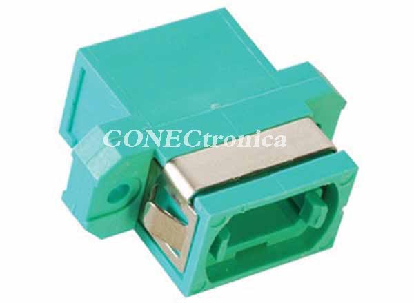
This anchor point is located in the cable gland. See Figure 10.
In addition to its securing function, the cable gland is responsible for maintaining correct polarity, forcing the connector keys into the proper position. To guarantee polarity, the cable gland must adhere to the same principle as trunk cables and patch cables: Key-up / Key-up.
Of course, only a male connector and a female connector are permitted in a cable gland. This requirement dictates the position of each connector type, male or female, within the network.
Given that patch cables (the mobile elements responsible for network management) must have the same type of connector at both ends, and that these are the only elements that can connect to the connectors on optoelectronic devices, it follows that the connectors on a patch cable must be compatible with those on the telecommunications equipment. Since the equipment has MPO-M connectors, the patch cables must necessarily be made with MPO-F connectors.
This decision, in turn, determines the choice of connectors for the trunk lines, which make up the network's fixed infrastructure, specifying male MPO connectors (MPO-M), complementary to those used for patch cables.
In the exceptional case where a different type of connector is available at each end (MPO-F and MPO-M), as shown in Figure 4, it is referred to as a hybrid patch cable. This type of configuration is not recommended, as it would allow equipment to connect to the network but would not be suitable for assigning bridges between panels within the fixed infrastructure.
Base 2 and Base 12 Compatibility. Adaptation Modules.
From what has been discussed so far, it follows that, in a future-proof Data Center, polarity must necessarily be considered in its conception and design.
It seems clear that it is advisable to establish a fixed infrastructure with Base 12 polarity, and therefore Key-up/Key-up trunks, which allows the installation of high-speed transmission channels. However, reality dictates the need to maintain classic duplex links, supported by Base 2 polarity.
We will now explain which elements are required, and with what criteria they should be configured and used, to enable the management of Base 2 channels over Base 12 infrastructures.
Although, as we will explain below, there are many procedures to implement this integration, compliance with certain premises designed to facilitate administration limits the options in practice.
International standards provide specific guidelines for establishing duplex links over 12-fiber trunks. In particular, the ANSI/TIA-568-C standard defines three basic methods, identified as A, B, and C, capable of meeting this need, but also states that there are many criteria for modifying these three basic types, which may be convenient to apply to facilitate the management and future projection of the network.
To understand the unique characteristics and differences between the possible methods, we must first analyze the components that make up a channel.
Remember that constructing a channel requires all or some of the following elements:
- Main lines
- Bulkhead fittings
- Patch cords
To these fundamental components, we must add new elements that allow, where applicable, the adaptation of base stations: Adaptation Modules.
These modules are located at the ends of the trunk lines, before the trunk line connects to the administration panel. Therefore, they become part of the network's fixed infrastructure.
If certain design conditions are required for these elements to guarantee their correct operation and ease of management,
the number of possible adaptation methods is significantly reduced.
Under these premises, the criteria that must be applied are:
- That the trunk lines and cable glands are configured in Base 12, or, in other words, that they are of the Key-up / Key-up type.
- That the chosen method can function using only duplex patch cords and cable glands that comply with Rule AB (Base 2).
These requirements rule out all methods in which the adaptation relies on the arrangement of the fibers in the trunk lines, cable glands, or patch cords. Indeed, since the trunk lines and bulkheads are determined by Base 12 polarity and the duplex patch cords and associated bulkheads by Base 2 polarity, the chosen method is managed in the adaptation modules.
These constraints rule out methods A and C as potential candidates for the infrastructure of a modern data center, since the trunks of both are incompatible with the Base 12 polarity requirement. It is worth remembering that these two methods originated from the adaptation of classic trunks, which assigned fibers directly (1 to 1, 2 to 2,…) or inverted pair to pair (1 to 2, 2 to 1,…), respectively.
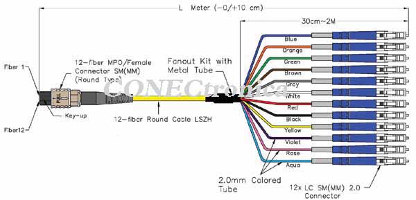
The adaptation module, known as the Hydra due to its appearance, is an element that, as already mentioned, is incorporated into the fixed infrastructure at the ends of the trunks and allows the free assignment of the 12 fibers to the corresponding ports associated with 6 duplex connectors. See Figure 11.
Hydras are usually grouped in pairs in a single common enclosure known as the Adaptation Cassette, which is typically installed in the network management panels.
Thus, the problem of transporting Base 2 channels through Base 12 fixed infrastructure is reduced to the correct allocation of the adaptation hydras in the duplex pass-throughs of the cassettes.
It can be verified that there are several possible configurations, a total of 46,080, that allow a fully effective Base 2 and Base 12 compatible network to be configured from Model B using a single adapter module. In these cases, the configuration of both complementary modules is identical. That is, the modules are self-complementary, allowing the use of the same module throughout the entire network, which simplifies its administration.
It is important to note that each self-complementary module is incompatible with any other self-complementary module.
Logically, in an infrastructure with fixed elements (trunks) equipped with male MPO connectors (with keys), the adapter modules must have MPO-F connectors. Although the reverse could also be considered, the advantage of configuring the trunks with MPO-M connectors has already been explained.
Conclusions
To design the fiber optic cabling system of a modern data center, a coherent solution must be chosen in which the set of constituent elements of its fixed, adaptation and connection infrastructure guarantee the coexistence of duplex Base 2 and parallel Base 12 and 24 polarities through simple and secure management.
For the construction of the fixed infrastructure, it is advisable to choose a Base 12 architecture implemented with factory-assembled, modular, key-up/key-up components. The most common practice is to use factory-terminated cables with MPO-M connectors at their ends, known as trunk cables.
For the mobile network, patch cords with MPO-F connectors are suitable for Base 12 channels, and LCD or SCD connectors, using Rule AB, are appropriate for Base 2 channels.
It is essential to ensure that adapters, cassettes, and hydras have MPO connectors appropriate for their position in the network. That is, if they are to be integrated into the fixed infrastructure, the MPO connector must be the same as the one used on the trunk cable.
All elements involved in the network must guarantee their proper functioning before use, with the aim of minimizing manipulation and the addition of intermediate elements when establishing the channels.
If these criteria are followed systematically, managing a data center with multiple telecommunications systems can be very simple, rewarding, and cost-effective.
Figures 12a, b, and c illustrate Methods A, B, and C. It should be noted that in Methods A and C, the adapter module is the same and unique, which makes sense considering that in these cases, Base 2 polarity is managed in the duplex patch cords (Case A) or in the trunk itself (Case C). Method B requires two modules, which can be configured differently, but in 46,080 configurations out of the several million possible, both modules are formally identical, allowing the use of a single module throughout the network and simplifying its administration.
Author: Francisco M. López Torres - Director of the OTP - Fibercom, SL.