Common Challenges in Cable Testing
Cables (waveguide, coaxial, or twisted-pair, for example) are by far the most widely used components in modern RF and microwave systems, such as mobile and data communications, satellite, or radar. They are also the leading cause of failure in these types of systems. Therefore, proper maintenance and the use of the appropriate testing tools are essential.
The typical cable testing process begins by determining whether a cable is defective or if its performance falls outside the desired specification. In such cases, it is necessary to locate the physical point of the fault along the cable. Once this location is determined, the fault must be identified and repaired. During maintenance and troubleshooting, engineers and technicians can pinpoint the location of a fault using return loss (RL) and distance to fault (DTF) methods, but they will not be able to determine the cause or type of fault, making repair difficult. In many cases, problems (e.g., loose or damaged connectors, water ingress, or broken solder points) cannot be identified simply by visually inspecting the cable.
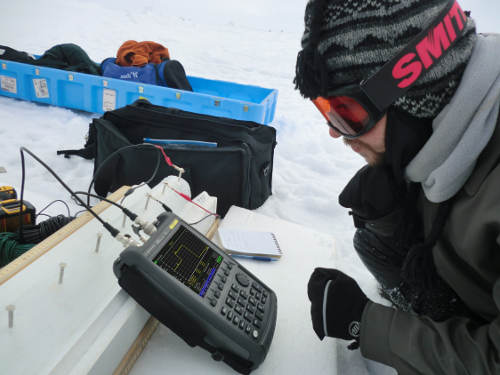
Another difficulty is that, until now, to measure cable performance, engineers and technicians have had to carry an antenna and cable analyzer, a network analyzer, a signal generator, and a power meter into the field. And when cables are used in systems located in hard-to-reach places or hazardous environments, the process becomes even more complicated. Once on site, the instruments have to be properly configured to perform the tests. Despite its effectiveness, this process can lead to errors, and the instruments can be damaged.
To further complicate matters, consider that vector network analyzers (VNAs) struggle to make accurate and repeatable on-site measurements of high losses in microwave cables whose test ports are far apart.
Easier Cable Measurements with the Enhanced FieldFox Test Package.
The new FieldFox Time Domain Reflectometry (TDR) cable measurement option (Option 215) complements the analyzer's existing RL and DTF measurements. The RL measurement capability identifies any mismatches in cable connections, while the DTF method pinpoints the location of faults or incorrect connections within the cable. The new TDR option allows engineers to obtain more data to measure impedance changes along the cable and identify the cause (type) of specific faults, whether they are short circuits, open circuits, or water ingress. To date, FieldFox is the only analyzer that allows RL, DTF, and TDR measurements to be performed with a single instrument.
FieldFox's Time-of-Distance (TDR) or step measurement uses the same data capture process as the DTF option. However, unlike the DTF method, this measurement characterizes the type of fault, including inductive or capacitive discontinuities. It does this by observing the waveforms reflected from a step propagating through the cable. By analyzing the duration, magnitude, and shape of the reflections, it's possible to determine the impedance variation in the cable. FieldFox's TDR measurement mode is only useful for DC-operated cables (e.g., two-conductor transmission lines).
To measure waveguides, FieldFox employs a bandpass time-domain transform technique. This is due to the waveguide's narrowband response, which limits the types of time-domain measurements that can be performed. Bandpass measurement is ideal for instruments under test with a limited frequency; however, it only provides the fault location. It is not possible to determine whether the discontinuity is inductive, capacitive, or resistive.
Another new option from FieldFox, Extended Range Transmission Analysis (ERTA, option 209), overcomes the challenges of measuring long microwave cables in the field. This portable solution measures scalar insertion losses in microwave cables with large distances between test ports and allows simultaneous access to both ends of the cable or waveguide.
Using a scalar analyzer as a signal source with a power sensor or broadband detector to measure cable losses can also be a slow process and prone to external interference; furthermore, it doesn't offer high levels of dynamic range. On the other hand, deploying a benchtop solution in the field is not recommended due to its large size and cost.
With the ERTA option, two FieldFox analyzers are deployed, one at each end of the cable being measured. One acts as the source and the other as the receiver, and their steps are synchronized via hardware triggering. Leveraging Keysight's unique InstAlign spectrum analysis technique, engineers and technicians can use this setup to perform highly accurate cable loss measurements without calibration or warm-up (Figure 1). It also offers best-in-class dynamic range, enabling measurements of long, lossy cables. Furthermore, this option can be configured with frequency offset for measuring devices such as mixers and converters.
FieldFox: The Most Complete Handheld Test Package.
In addition to FieldFox's new TDR and ERTA options, the analyzer offers several additional measurements, making it the most complete test package in a handheld instrument (Figure 2). These additional measurements include:
• RL, VSWR, and DTF for broadband and passband cable subsystems
• S-parameters, group delay, phase, Smith chart, and time-domain analysis
• Conversion loss/gain on the frequency converter
• Mixed mode, 1-port S-parameters, and time-domain analysis
Practical Examples
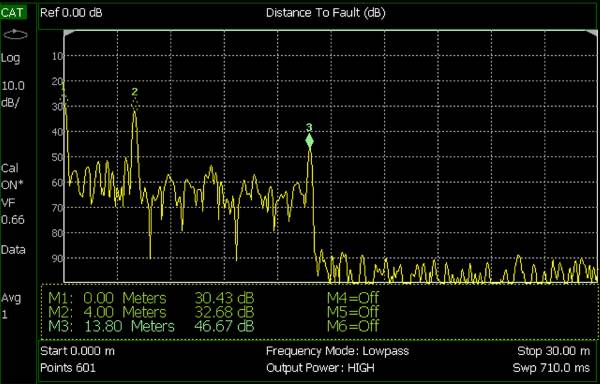
To better understand how FieldFox time-domain measurement techniques help identify the location and cause of cable faults, let's take the example of two short, 50-ohm coaxial cables connected together with a coaxial adapter. The shorter cable is connected to port 1 on the FieldFox, while the second is terminated with a 50-ohm load. As shown in Figure 3, a DTF measurement of the cables proves very useful in locating discontinuities.
Note that the markers are located at the three peaks of the measured DTF response. The peaks represent the magnitude of each reflection from the discontinuity. Marker 1, representing the interface between the calibrated FieldFox instrument and the first coaxial cable, indicates a distance of 0 meters. Marker 2, located at the adapter between the two cables, registers a distance of 4 meters. This also indicates that the length of the first cable is 4 meters. Marker 3, located at the 50-ohm load, shows a distance of 13.8 meters. From this data, we can calculate the length of the second cable (13.8 m – 4 m = 9.8 m). The observable drop in the measured amplitude to the right of the 50-ohm load indicates the end of the cable. Because this reflection measurement represents two-way signal paths, FieldFox adapts the marker values and x-axis format to the appropriate one-way lengths.
Let's now consider a coaxial cable with damage in two areas (Figures 4A and 4B). Fault A is a bend in the cable that has exceeded the manufacturer's specified minimum bending radius of 1 inch. In fault A, the cable has been bent well beyond the permissible radius, so this portion of the cable creates an unwanted reflection. Fault B is a cut in the cable's outer conductor. Part of the braided shielding has been lost, exposing the internal dielectric material of the coaxial cable. Both faults can be examined using FieldFox's DTF and TDR modes, but only the TDR measurement will be able to characterize the type of fault.
Figure 4C shows the measurement of the damaged cable using FieldFox in TDR mode. As we can see from the TDR response, the cable impedance is typically 50 ohms throughout most of the time-domain response, until a discontinuity appears. The discontinuities occur at the input connector, the fold of fault A, the cut of fault B, and the 50-ohm termination at the end.
Of all the cable discontinuities, the break indicating fault B exhibits the greatest mismatch, which can be seen by the magnitude of the corresponding peak. The break in the TDR response shows a single peak in the positive direction, implying inductive mismatch. This is common in cases of breaks in the outer conductor of a coaxial cable. In general, if the cable terminates in a load with a resistance lower than the characteristic impedance, the TDR response will show a step in the negative direction. If the load resistance were greater than the characteristic impedance, the TDR response would show a step in the positive direction.
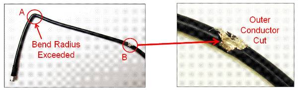
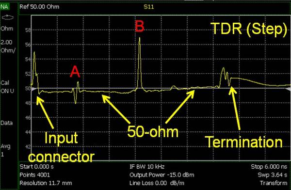
Figure 4. The top left (A) and top right (B) images show damage to a coaxial cable. The bottom image (2C) is obtained by measuring the damaged cable using the FieldFox TDR option. FieldFox can identify several types of discontinuities in TDR mode, including: R > Z0, R < Z0, inductive, and capacitive.
Summary:
Cable testing in the field can be complex. Determining whether a cable is faulty is only the first step. Next, engineers and technicians must identify the physical location and cause of the fault. Various time-domain techniques can be used for this purpose. FieldFox's comprehensive suite of cable testing capabilities, including the new TDR and ERTA options, is the ideal solution for testing any cable system in the field. FieldFox's TDR and DTF time-domain measurements pinpoint the location and causes of faults in coaxial cables, while the bandpass measurement detects the physical location of faults in waveguides. With FieldFox, engineers and technicians now have a faster and easier way to test cables in the field.
For more information on transmission line modeling or time-domain measurement techniques, see our Keysight cable testing webcast at www.keysight.com/find.fieldfoxwebcasts and the FieldFox cable testing application note at www.keysight.com/find/fieldfoxapps.
Tom Hoppin, Keysight Technologies, Inc.*
*Keysight Technologies Inc., formerly the electronic measurement business of Agilent Technologies
About the author:
Tom Hoppin is an applications consultant at Keysight Technologies. Tom began his career as an avionics technician in the United States Marine Corps. He joined Hewlett-Packard in 1973 after his military service. Over the years, he has held various engineering and management positions at HP, Agilent, and now Keysight, focusing on test system design and spectrum analysis. Tom retired in 2009. However, he has returned to Keysight as an applications specialist for its handheld RF and microwave analyzers.