
2. Project Creation:
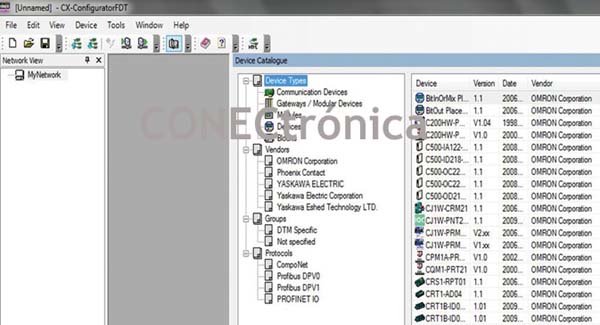
CxConfiguratorFDT is the advanced integration and configuration tool for Profinet networks. CxConfiguratorFDT supports devices from OMRON and other manufacturers, as will be discussed in a later section.
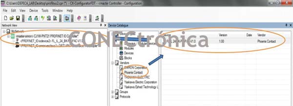
A "Device Catalog" list, featuring various Profinet-IO component manufacturers, is available on the right side of CxConfiguratorFDT, as shown in Figure 2.
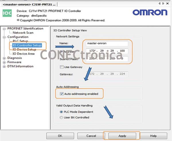
2.1. Configuring the Controller Device (Profinet Master)
To configure the network master, access the “IO Controller Setup” section (Figure 3) and provide the network controller name, the controller's IP address, and its subnet mask. Select 'Auto-Addressing' for assigning addresses to the I/O module areas.
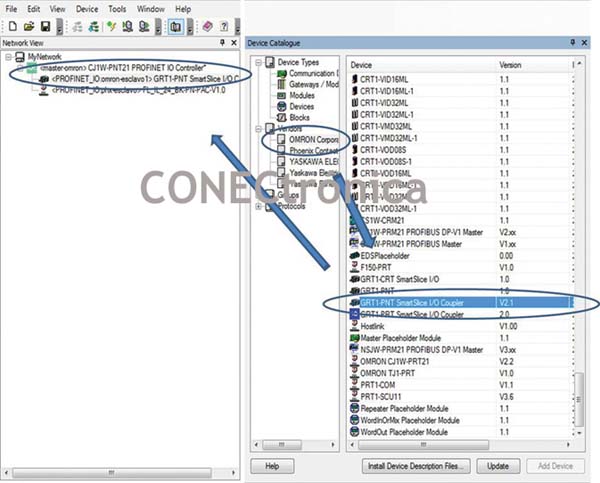
2.2. Profinet-IO Slaves
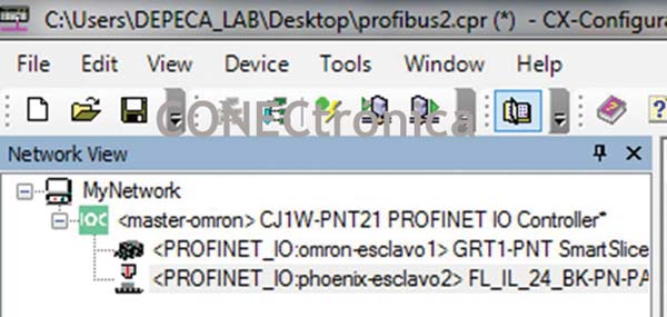
From the “Device Catalogue” it is possible to drag and drop the OMRON GRT1-PNT SmartSlice I/O Coupler device to the Profinet network (Figure 4).
For configuring Profinet devices, use 'IO Device Setup' (Slaves). The device list will display all devices added to the controller in the network view. Selecting the master in the 'IO Device Setup' window allows you to edit various communication parameters.
"Watchdog Time" determines how long after the last data exchange the device should consider the connection lost.
“Data Hold Time” determines how long an I/O device will retain its outputs after the last valid data exchange with the I/O controller. When configuring redundant controllers, this field should be greater than the Watchdog factor to prevent problems during controller replacement.
For each device, the following can be edited:
- Device Name: This is used as the identifier for the I/O device. Use only lowercase letters (Profinet specifications).
- IP Address: This is configured by the controller when the I/O device starts up.
- Update Rate.
2.2.1. Configuring the GRT1-PNT Header
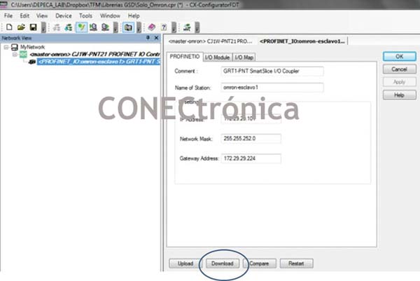
: Select the master in the network view window. In the "Configuration" section, under "IO Device", modify the device name and/or IP address if necessary (Figure 5).
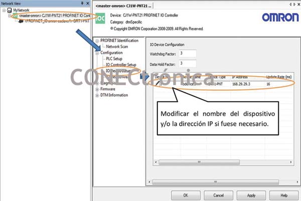
The rest of the Profinet parameters do not need to be modified.
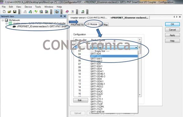
2.2.2. Configuring I/O Modules
Select the slave and then the “I/O Module” tab. Double-click each slot to select the module. Configure all slots containing an I/O module. If a GRT1-END-M is present, it must also be configured. To save the changes, click 'Apply'. As illustrated in Figure 6.
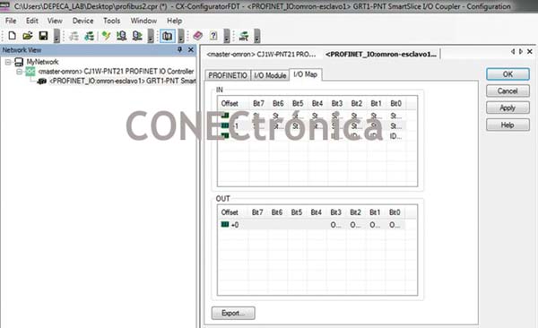
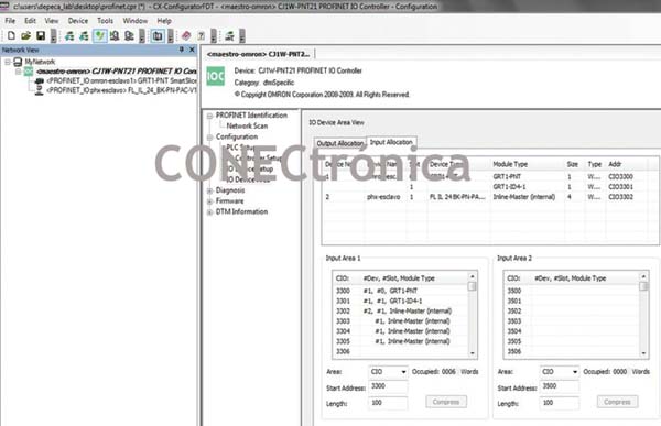
2.2.3. Viewing the I/O Map
By selecting the slave and then the “IO Map” tab, you can see the layout of the input and output area tables of the GRT1-PNT. The I/O Map tab is left at its default settings (Figure 7).
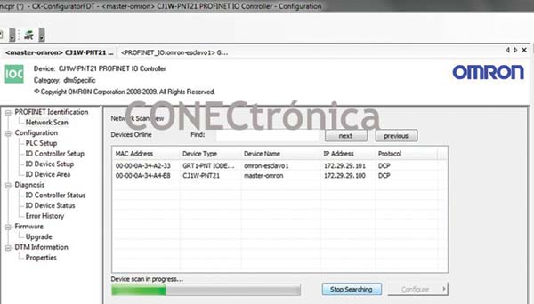
2.3. Assigning Names/IP Addresses
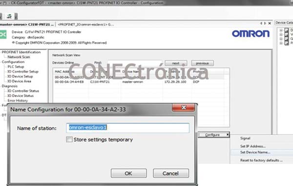
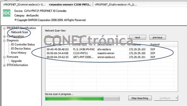
: Select the CJW-PNT21 Profinet-IO Controller header in the “Profinet Identification” section and scan the network with “Network Scan”. This will display the devices connected to the network. This is illustrated in Figure 8.
To change the device name, select the device and then press 'Configure' ? 'Set Device Name…', as shown in Figure 9.
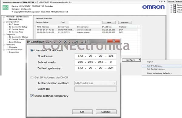
To change the IP address of devices, select the device and click 'Configure' > 'Set IP Address…'. It is not strictly necessary to configure the IP address from this option. The Profinet-IO controller configures the device address using the assigned name and the 'IO Device Setup' settings. Therefore, it is essential to ensure that the same device name is entered in both the 'Network Scan' and 'IO Device Setup' options. The IP address change process is illustrated in Figure 10.
2.4. Integrating Profinet-IO Slaves from Other Brands
Sometimes it is necessary to communicate with devices that are not included by default in the "Device Catalogue". To insert a device into a Profinet system, you must use the device's GSD file. Each device has its own GSD file (with an electronic data sheet), which is a text file containing hardware and software revision details, device timing information, and cyclic data change information.
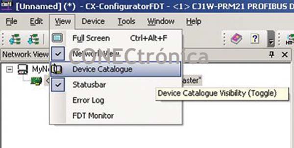
From the manufacturer's official website, you can download the GSD file for the FL IL 24 BK-PN-PAC Profinet-IO communications unit to insert a new device into the CxConfigurator Profinet libraries. From the View menu in the main menu, open the "Device Catalogue" (Figure 11).
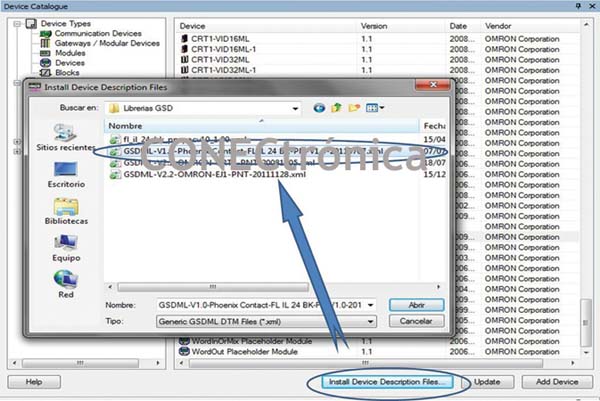
Click on “Install Device Description Files” to add the FL IL 24 BK-PN-PAC to the device catalog (Figure 12).
2.4.1. Integration of the Phoenix FL IL 24 BK-PN-PA Profinet-IO Slave
From the “Device Catalogue” it is possible to drag and drop the Phoenix Contact FL IL 24 BK-PN-PA device into the Profinet network. As illustrated in Figure 13.
In the device list, all devices added to the controller in the network view will appear. Select the master in the network view window. To configure parameters, double-click the Profinet-IO FL IL 24 BK-PN-PAC device in the network view window (Figure 14).
2.4.2. I/O Modules
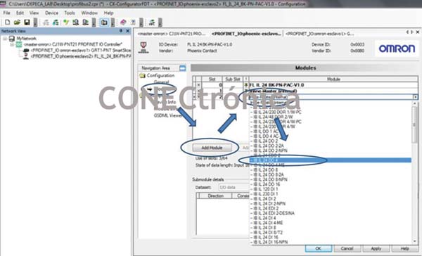
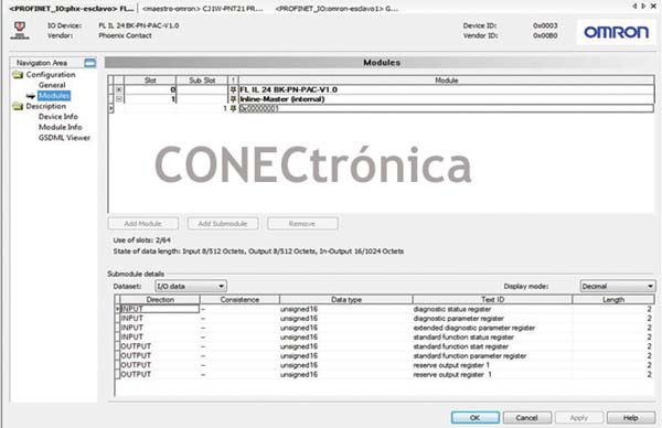
In the “Modules” option, click on “Add module” to add a module connected to the Profinet-IO header. Click again on 'Inline-master (internal)', and select the type of device of interest (up to 64 I/O devices can be added). As illustrated in Figure 15.
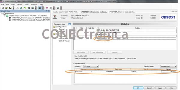
In the tree of each module (Figure 16) you can see the type of 'IO Data' variables generated by each module, also, you can see the diagnostic records of the header (Figure 17).
3. Network Startup
3.1. Controller Configuration Next, by connecting to the PLC, the network configuration is transferred to the Profinet controller. In the project tree, select “Go Online” for the controller from the context menu. If communication is successful, “Connected” will appear at the bottom of the window, as illustrated in Figure 18.

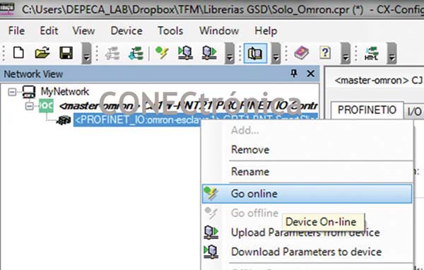
Select GRT1-PNT in the “Network View” window (Figure 19). Right-click and select 'Go online'.
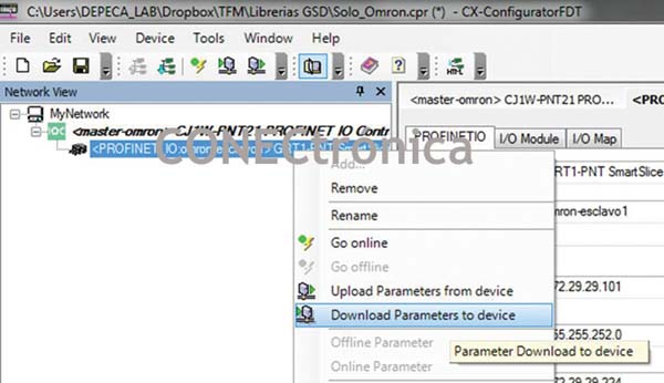
Select the I/O Module tab and click 'Download' (Figure 20) or from the network view window, in the context menu 'Download Parameter to device'. As shown in Figure 21.
3.2. Integration Diagnosis
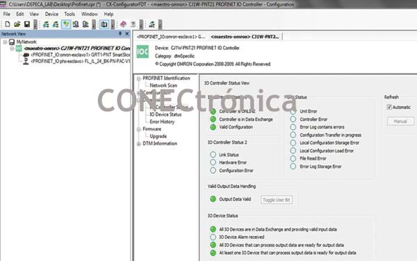
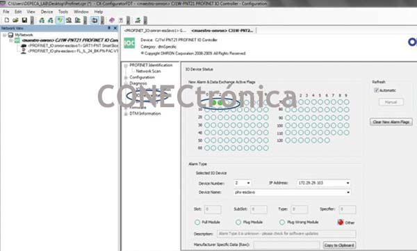
Once the transfer is complete, its correct operation can be verified by selecting the master unit and viewing the network status in “Diagnosis.” Figure 22 shows the status of the Profinet Controller, “IO Controller Status.” The refresh was performed manually, but it can also be done automatically. Clearly, the controller is “ONLINE” and its configuration is valid. The same procedure is followed to view the status of the slaves from the “IO Device Status” window (Figure 23).
The configuration has been completed and uploaded to the PLC. From Network Scan, by clicking on the “Search Devices” button, you can view the network device configuration. This is illustrated in Figure 24.
3.3. Using Profinet Data
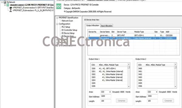
The Profinet network inputs and outputs are treated as if they were modules directly connected to the PLC rack. Figures 25 and 26 show the addresses of each module for the PLC, including diagnostic addresses.
The next article will show the configuration of a Profinwet multi-master network.
Author:
Alfredo Gardel, Ignacio Bravo, José Luis Lázaro, Arley Vanegas


