
Physical measurements of things like temperature, pressure, proximity, or light are transformed into digital information for the system to process, and then the results of the calculations are converted into physical actions of real devices, such as valves, fans, power supplies, gauges, etc. Information technology (IT) and operational technology (OT) networks tend to use similar technologies to facilitate the flow of data throughout the organization.
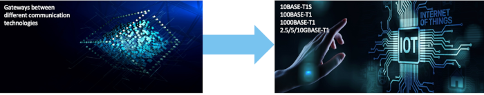
One way to bring IT and OT closer together is to use a single underlying network for communication between multiple systems. When electronics first entered the realm of automation, various distributed subsystems became specialized and defined by the hardware they used. Communication technologies, optimized for specific applications, were defined for these domain-specific hardware architectures. Each used specialized buses for communication, requiring complex gateways to translate communication protocols from one hardware system to another.
Over time, centralized, software-defined architectures are replacing outdated approaches. Instead of separate, independent domains or functions, electronic interfaces are grouped into zones within an enterprise and connected to a modern, centralized computing platform. They use the now ubiquitous Ethernet technology to transport data to where it is needed. Ethernet is scalable. A single software stack can utilize different physical hardware layers to move information at varying speeds without altering the data itself. A single Ethernet frame format is used, regardless of the bandwidth of a given Ethernet link. Ethernet switches automatically adjust the data transmission rate on each of their ports.
At the network edge, various sensors (temperature, pressure, light, proximity, etc.) collect data from the physical world and convert it into digital information. Once processed, actuators (motors, lights, fans, valves, etc.) translate the digital data into physical actions. These devices typically don't require large amounts of data, but it's important that the wiring is simple and easy to install. 10BASE-T1S Ethernet technology was developed for these applications and brings Ethernet architecture to very simple devices. Figure 1 illustrates this technological trend.
Hardware-defined Software-defined
- Domain-specific hardware. - Zones connected to centralized processes
- Multiple application-specific buses - Ubiquitous IP-based Ethernet network
- Distributed walkways - A package format
- Complex cabling - Low-cost, single-pair, and multipoint edge cabling
Figure 1: Trends in networks
10BASE-T1S Technology
Ethernet 10BASE-T1S was developed specifically for these zonal architectures. It operates at 10 Mbps over a single balanced pair of wires. 10BASE-T1S technology builds upon the simple mechanisms used when Ethernet first became a standard over 40 years ago, but improves upon them to utilize the full available bandwidth more effectively.
Ethernet initially used a single coaxial cable to which multiple devices were directly connected. The switches widely used today were developed later to eliminate the shortcomings caused by the multipoint nature of the original scheme. However, they introduced complexity and cost, and led to the need for unique point-to-point connections between a device and a switch.
The original Ethernet worked by using multiple devices that detected the line they were connected to and then attempted to transmit data. If only one device started transmitting, it could send a complete packet of information. If multiple devices tried to transmit at the same time, a collision would occur on the line, which all devices would detect. The devices would shut down and try again after a random amount of time. This technology was called CSMA/CD (Carrier Sense Multiple Access with Collision Detection). Its main drawback was that as more devices were connected to the single-wire backbone, more collisions occurred, and more and more time was wasted backing up and retrying. The effective bandwidth of the link became very limited.
Physical Layer Collision Prevention (PLCA)
Ethernet 10BASE-T1S solves this problem by introducing an arbitration mechanism called PLCA (Physical Layer Collision Avoidance). PLCA is designed for half-duplex and multidrop networks like 10BASE-T1S, and eliminates the problems associated with CSMA/CD in multidrop segments.
With PLCA, the transmission cycle begins with a signal sent by a coordinating node (Node 0) that the network nodes use to synchronize. After sending the signal, the transmission opportunity passes to Node 1. If it has no data to send, it yields its opportunity to Node 2, and so on, continuing the process until each node has been offered at least one transmission opportunity. The coordinating node then initiates a new cycle, sending another signal.
To prevent a node from blocking the bus, a "jabber" function interrupts a node's transmission if it exceeds its allotted time, allowing the next node to transmit. The result is no impact on data throughput and no data collisions on the bus. CSMA/CD can exhibit random latencies caused by data collisions. PLCA provides a guaranteed maximum latency and other features that overcome these limitations. Figure 2 illustrates how PLCA works.
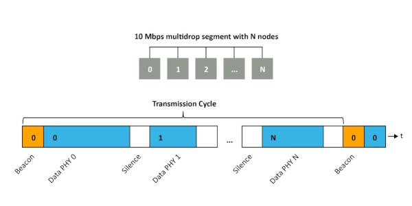
Figure 2: Physical Layer Collision Prevention (PLCA)
Security
Once the bits and bytes of data are retrieved from the thread that carried them from one device to another, they are delivered to higher software layers in a standard Ethernet packet format. This format has a destination address, a source address, some management bits, and a payload. The format does not change with changes in the physical layer. This means that the software layer remains constant even when network speeds change as more and more data is added for processing by a computer system. Figure 3 illustrates the general concept.
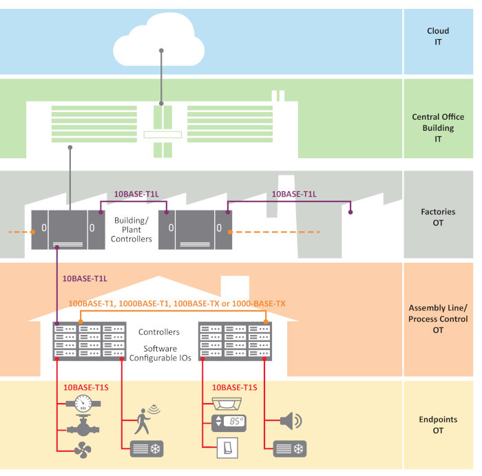
Figure 3: Ethernet from the edge to the cloud.
Instead of having multiple buses and protocols at the endpoints of an OT network, Ethernet mechanisms can be used to connect to these devices. All of these can be addressed using well-established Ethernet mechanisms.
This includes security mechanisms to prevent data intrusion or espionage, or worse, interference with the physical systems that use the data. Ethernet is used in very high-security applications, such as banking, because the cyber resilience of Ethernet networks is well-developed. Other specialized communication technologies may have few or no cybersecurity features. They would have to be developed and then maintained. The logistics of providing these features would also need to be put in place. This logistics can be more complex than the design and manufacture of a hardware product. Controlled-access facilities are needed, and breaches in the chain of trust can occur at any point in the supply chain. There are very few semiconductor vendors prepared to handle this task.
Ethernet is an integral part of the data analytics infrastructure. Big data is used to analyze trends and provide services. Predictive maintenance, remote diagnostics, and other monitoring services require access to all the data in a system, and Ethernet can provide access to the most remote corners of an industrial infrastructure. This goes hand in hand with enabling software to manage various processes and allow for dynamic adjustments as technology evolves.
Functional Safety
The use of standardized technology, such as Ethernet, also simplifies the development of functionally safe systems. Functional safety means that when something in a system fails, the system can react predictably to safely prevent further problems. Different industries have different standards. For example, the automotive industry uses ISO 26262. Industrial applications use IEC 61508. Medical, consumer, and other applications have their own standards. However, they are all similar. Functional safety applies to entire systems, but system designers must ensure that the components they use are functionally safe in order to certify the entire system.
Semiconductor components, for example, must be accompanied by functional safety manuals that analyze and diagnose the effects of failure modes. This is known as FMEDA (Failure Modes, Effects, and Diagnostic Analysis) and is a method for determining the causes of failures and their impact on the system. It is applied in the early stages of system development to detect and correct any weaknesses.
Summary
10BASE-T1S Ethernet technology creates new business opportunities for connecting OT and IT networks that require interoperability and security. Data can be accessed from nodes at the network edge and used to enable new intelligent predictive services, as well as asset management and tracking solutions.
System costs are reduced through simplified components, software design, and cabling. Gateways are eliminated. The number of switching ports used is reduced because multiple devices connect to a single bus line via single-pair cabling.
Risk is reduced through the use of unified interfaces and well-established security mechanisms. 10BASE-T1S Ethernet complements legacy solutions at the edge of IoT networks. It enables unified design, software development, testing, and maintenance across all levels of OT and IT networks. Simpler architectures with enhanced security reduce risk for designers and enable functionally secure systems.
Author: By Henry Muyshondt, Senior Marketing Director, Automation Information Systems Business Unit, Microchip Technology


