VME MIL-COTS chassis manufacturers continue to deliver advanced developments by incorporating cutting-edge technology with higher power levels in VME chassis and slots of the same size. This increases the pressure on VME MIL-COTS power board manufacturers to supply power boards capable of achieving higher power while simultaneously limiting the number of power slots required. Furthermore, the power supply must be able to operate under extreme conditions of temperature, shock, vibration, and humidity.
A new technology—called Factored Power Architecture, and provided by V·I Chips—is the primary reason for achieving higher power board density in a robust miniature package. More specifically, the reduced height of the V·I chip is the main reason the power board could fit into a single slot. The aluminum baseplate channels the heat generated by the chips to the edge of the board, where the chassis rails dissipate the heat. Conventional power converters are simply too tall to meet this requirement.
The assembly was an important aspect, especially regarding thermal issues. Several additional factors were needed to overcome the heat problem: the improved efficiency of the V·I Chips, a thermal gap filler material, and the fact that the V·I Chips had a lower profile, allowing sufficient metal thickness on the motherboard to enable a thermal path to the side rails. Furthermore, the chips' high efficiency resulted in better heat dissipation in the smaller space, and they offered a wider operating temperature range, which also helped.
The thermal gap filler was a second important factor in achieving the single-slot design. It consists of a soft, malleable, two-component mixture applied to the top of the chip's VI, enabling the design to dissipate heat from the chips. A secondary problem was that downward pressure cannot be applied to the VIs without causing damage. With the use of the thermal gap filler, no such pressure is exerted. An additional problem is that chip height tolerances are imprecise (since these are surface-mount J-pins), making it impossible to ensure identical chip heights and thus achieve good contact with the heatsink. The use of Bergquist's thermal gap filler provides a good thermal path to all chips without any downward force on any of them.
Finally, VME board manufacturers often require additional EMI filtering to meet MIL standards. With the addition of an input attenuation filter/filtering module (M-FIAM5B), no additional EMI filtering is required with the single-slot power card.
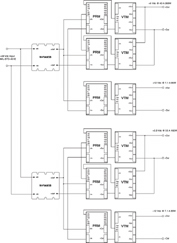
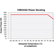
Figure 1 shows the unit, Figure 2 shows the block diagram, and Figure 3 shows the power loss curve for
the single-slot power supply board. Table 1 summarizes the specifications.
As shown in Figure 2, the unit is formed with 12 V·I chips (six PRMs and six VTMs). It also uses two militarized attenuator filter modules at the input; these components are described below.
The PRM is a non-isolated, efficient regulator capable of boosting or buckling a wide range of input voltages. It is specifically designed to supply a factored bus distribution voltage to power the VTMs located downstream as fast, efficient, isolated, and low-noise point-of-load (POL) converters. Together, the PRM and VTM form a complete DC/DC converter subsystem that offers the advantages of high density and efficiency; low-noise operation; architectural flexibility; fast transient response; and elimination of bulky point-of-load capacity.
Table 1. Specifications
(25°C, nominal line, 100% load unless otherwise stated)
Meets the normal range of MIL-STD-704F
22 VDC to 29 VDC, 28 VDC nominal.
DC input voltage 50 VDC. 12.5 ms transient,
longer shutdown for auto-restart.
Shutdown for auto-restart in abnormal range.
DC input line current 23.5 A max at 22 Vdc; 18.5 A typical for 28 Vdc input
Input power 518 W max
Output power 450 W max, all outputs combined
+5 Vdc, 40 A, 200 W
Output voltages +3.3 Vdc, 55 A, 182 W
+12 Vdc, 7.1 A, 85 W
-12 Vdc, 7.1 A, 85 W
Efficiency 85% min
Start-up time 500 ms max
Voltage adjustment ± 1%
Temperature regulation ± 0.01% / ºC
Line/Load Regulation: Line: ± 1%; Load: 1.2%±
50 mV peak-to-peak max (20 MHz
output ripple bandwidth), all except ± 12 Vcc: 100 mV
peak-to-peak max (20 MHz bandwidth)
Current limit, short-circuit protection,
automatic
-40°C to +65°C, measured on the motherboard,
conductive cooling with blocking wedges up to 400 W.
-40°C to +55°C, measured on the motherboard,
conductive cooling with blocking wedges up to 450 W.
-55°C to +100°C, not operational
Size 6U x 4hp x 160 mm
Typical weight 1.1 kg
Connector 1 Positronics PCIH47 M400A1
Shock and Vibration MIL-STD-810 Ground Mobile
Humidity 0-95% non-condensing
EMI MIL-STD-461E CE102, CS101
The VTM provides fast, efficient, and quiet fixed-factor voltage division (or current multiplication). With twelve voltage division factors between 1:1 and 1:32, the standalone VTM gives the user the flexibility to deliver up to 100 A or 120 W for any output voltage between 1 and 50 VDC in a surface-mount package approximately 1 square inch in size. Military VTMs are optimized for use with the Military PRM to implement a Factored Power Architecture (FPA). Together, the PRM™ + VTM FPA chipset provides all the functionality of a DC/DC converter, but with higher levels of performance and flexibility, in a rugged miniature package.
The M-FIAM5B, a COTS input filtering attenuator module with a 20 V input voltage, is a DC input stage module that provides EMI filtering and transient protection. It allows designers to meet the MIL-STD-461E susceptibility standard and the MIL-STD-704E/F input transient standard. It accepts an input voltage of 14–36 VDC and supplies an output current of up to 20 A. The M-FIAM5B is offered in a standard “half-brick” module measuring 2.28 in x 2.2 in x 0.5 in,
and depending on the model selected, it can be surface-mounted or recessed into the board for applications where height is critical.