
In this article, we'll discover just how ubiquitous the USB interface is, see how the standard has evolved, and discuss the changes the USB connector type has undergone.
Wherever you are: USB.
It's easy to underestimate the enormous impact the USB interface has had on how we adopt and interact with technology on a daily basis. Since its inception a couple of decades ago, USB connectors have become as common as house keys. Often, we plug in a USB device and forget about it, like a desktop computer keyboard. In other cases, we might plug and unplug it several times a day, like a mobile phone in a car's infotainment system. At night, many of us plug our phones, fitness trackers, or tablets into USB AC outlets to charge them and have them ready for the next day. USB connectors are increasingly used for power rather than data transfer, demonstrating just how dependent we've become on this interface.
The Evolution of USB:
The first category of the Universal Serial Bus (USB), USB 1.0, was launched in 1996 by the USB Implementers Forum (USB-IF). Its establishment was supported by some of the leading hardware vendors of the time, such as Compaq, DEC, IBM, Intel, Microsoft, NEC, and Nortel, with the original idea of establishing a standard method for connecting computers and peripherals.
The explosive growth of desktop computers and peripherals (external hard drives, keyboards, mice, printers, webcams, portable media players, etc.) led to the development of many connection methods, some of which were proprietary. The lack of a standard connection limited market growth for the various independent peripheral manufacturers. In the mid-1990s, the common methods for connecting peripherals were the RS232 serial port and the Centronics parallel interface; neither of these methods provided power, and both required some technical knowledge for configuration. Other connectors included IBM PS/2, DIN, and SCSI.
From the outset, the USB specification required a simple interface. This meant it needed no configuration and could be plugged in and unplugged while the computer was running, allowing devices to be added and removed without interrupting the operation of the host computer. Almost all corresponding peripherals required power, so USB 1.0 had a capacity of 5 VDC/0.5 A/2.5 W. By powering the peripheral, there was no longer a need for additional cables and power supplies. USB also specified a small number of connector types for peripherals and the host device. The electrical characteristics were extremely simple: a four-wire cable, two for power and one twisted pair for data. During the first decade of USB, numerous types emerged, although many are now obsolete. Sometimes, the connector specification, such as Type A, was confused with the bus specification, such as USB 3.1 (see Figure 1).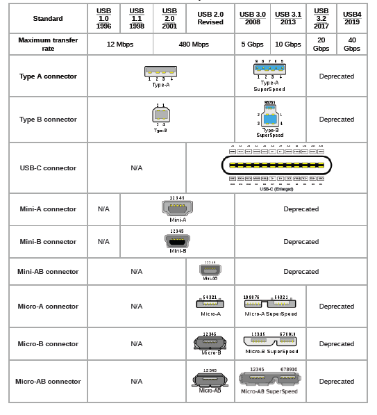
Over the years, the USB specification has continued to evolve, both in terms of data signaling transfer rates and power delivery. The original USB 1.0 established two signaling rates (12 Mbits/s and 1.5 Mbits/s). To minimize technical terminology for the general public, each speed specification had a non-technical name. The 12 Mbit/s standard was called "USB Full Speed," and the 1.5 Mbit/s standard was called "USB Low Speed." The USB-IF maintained this strategy with USB 2.0 in 2000 (the 480 Mbit/s standard was called "High Speed"), and in 2008, USB 3.0, with a capacity of 5 Gbit/s, became known as "SuperSpeed USB" (see Figure 2).
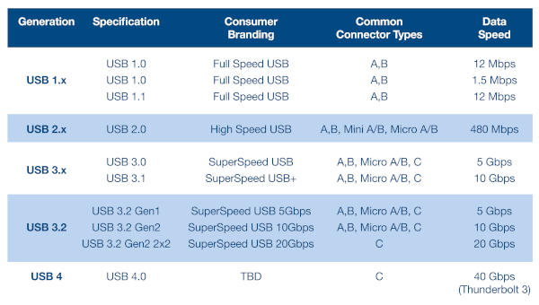 In 2013, USB 3.1 SuperSpeed+ offered speeds up to 10 Gbit/s, and USB 3.2, in 2017, introduced a dual-lane method, doubling the rate to 20 Gbit/s. In just over a decade, transfer rates increased 1666-fold, and USB adoption quickly became widespread. USB also outperformed other competing technologies at the time, such as FireWire, Apple's faster but more complex method.
USB 3.0 enabled several iterations of data transfer speeds and, more importantly, the announcement of the USB-C connector. This connector is notable for its compatibility with an even wider range of devices and the fact that it doesn't need to be plugged in oriented in a specific way. USB-C has quickly established itself as the primary method for charging and powering portable devices, from mobile phones to laptops. Its power capability has expanded to that of a conventional power adapter. Furthermore, USB-C and USB 3.0 introduced a distinct range of output voltages: 9, 12, 15, and 20 V.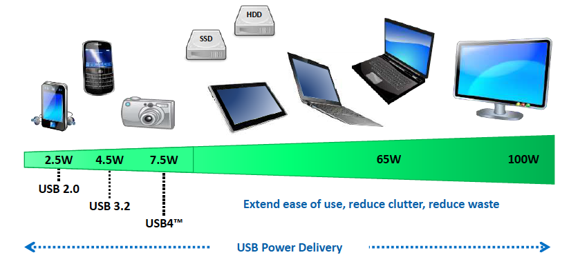 USB has always strived to maintain its original objectives. Cable lengths have remained relatively short, with the idea being to connect devices in the same physical location as the main device, rather than for networking. Additionally, the connection topology requires all communication to pass through the main controller. Devices cannot connect and communicate directly with each other.
USB Architecture and Concepts:
USB operates using a multi-level star topology, where the main controller or "upstream" host device is typically located on a computer. A maximum of 127 devices can be connected to a single controller via multiple hubs. Connected peripherals are categorized according to their class (HMI, multimedia transmission, etc.). Each device, such as a keyboard, is uniquely identified by an address and, typically, three logical connection point channels. Each connection point has a specific function, and the specification allows for up to 32 connection points on a single device (see Figure 4).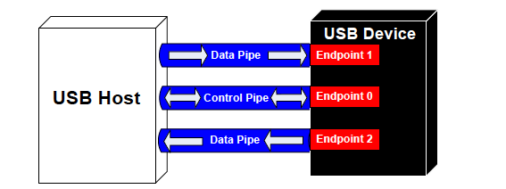
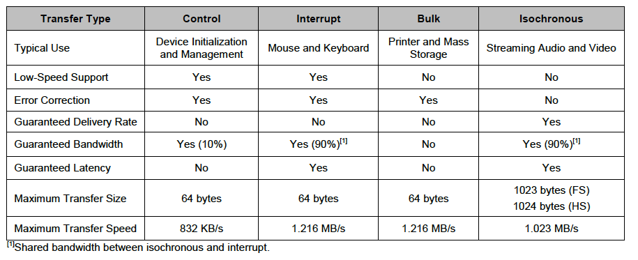
Communication between the host controller and the device occurs via bidirectional channels, both control and data. The functions of these channels depend on the device class, which generally defines the data transfer types. There are four data transfer types: control, interrupt, bulk, and isochronous.
Figure 5 illustrates the attributes of each data transfer type, with an example use case for each.
The device initialization (enumeration) process occurs when a USB device is connected to a host controller. This step involves the host sending a reset signal to the device and requesting parameters to determine its class and transfer rate. Upon receiving this information, the host controller assigns the device a unique 7-bit address, after which communication can begin.
 For a more detailed and technical explanation of USB architecture and operation, you'll find helpful resources on the USB-IF website. Infineon (formerly Cypress) application note AN57294 also provides a detailed explanation of USB 2.0 operation.
The USB4 specification, thanks to continuous evolution:
In late 2019, the USB-IF announced the USB4 specification. Building on USB 2.0 and USB 3.4, USB4 is primarily based on the Thunderbolt protocol. Data transfer speeds of up to 40 Gbps are achieved through two lines with USB Type-C connectors and certified cables. Many data and display protocols can effectively share USB4's maximum bandwidth capacity. Backward compatibility with USB 2.0 is maintained, and, as a new feature, USB4 is compatible with Thunderbolt 3 devices. The USB-IF has set as one of USB4's objectives to lead the convergence to USB Type-C in the future, in order to avoid the confusion created by many older connector types. Some creative sectors, such as animation and video editing, have long benefited from Thunderbolt 3's excellent transfer rates, so its integration into USB4 will open the door to many new use cases. USB4 can also include other popular transfer protocols, such as PCIe and DisplayPort.
For a detailed introduction to USB4, the USB4 System Overview will be of particular interest.
The USB-IF continues to establish testing and compliance services for device manufacturers. Because USB-C has become established in charging and power applications, while USB4 is expanding into a wider range of peripherals, the USB-IF has created the EnablingUSB , where the new logos used to inform consumers about product certification are displayed.
USB Products
offers a wide range of USB products from leading distributors to assist engineers during the development and production of USB applications.
Examples include a range of USB Type-C evaluation modules from FTDI Chip. The FT233HP and FT4233HP modules provide high-speed USB Type-C connectivity with two Type-C ports. One port can function as a power sink or a power supply port. The second port can only function as a power sink. The ports support multiple USB 3.0 power profiles, ranging from 5 to 20V. Host serial connectivity options include UART, SPI, I2C, and JTAG. The modules also include FTDI's high-speed USB bridge ICs, the FT233HP and FT4233. These USB 3.0 devices feature a 32-bit RISC controller and offer backward compatibility with the USB 2.0 standards of 480 Mbps and 12 Mbps.
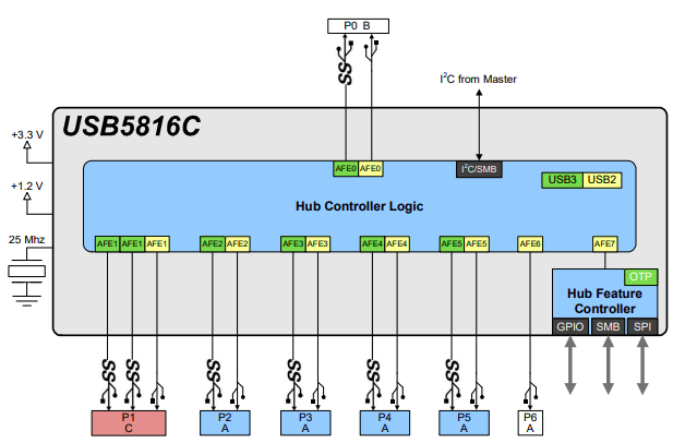
The USB58x and USB59x (Microchip Technology) of USB 3.1 Gen 1-compatible smart bridge ICs can implement six or seven USB 3.1 Gen 1 downstream ports and incorporate Microchip's port splitting technology, which allows a single USB downstream port to be used for both USB 3.1 and USB 2.0 devices simultaneously. The bridging capabilities of the USB58 and USB59 enable seamless use of I2C, SPI, or GPIO interfaces over USB. The Microchip EVB-USB5816 is an ideal demonstration and prototyping platform for the USB5816 of bridge ICs. Figure 5 illustrates the internal architecture of the Microchip USB5816 bridge IC, showing the six downstream ports and one upstream port.
 In USB power applications, the Infineon/Cypress EZ-PD CCG3PA USB Type-C controller is ideal for various mobile and tablet charging applications. It utilizes an Arm Cortex-M0 processor core and features protection against system failures (such as low voltage, high voltage, or high current output); it also complies with the USB-IF Power Delivery 3.0 specification.
USB: Getting Stronger.
The Universal Serial Bus has become the ultimate short-range, high-speed wired interface for virtually any type of device. In recent years, with the advent of USB Type-C connectors and the emphasis on power delivery, USB has taken further steps to increase its appeal and popularity.
Integrating USB connectivity and power delivery capabilities into design specifications is essential for hardware engineers and embedded system developers. Major semiconductor vendors offer a wide range of USB-IF-compatible interfaces, controllers, and power ICs that can be used as the foundation for a design. Evaluation boards, development kits, and reference designs help accelerate the process from initial design concept to reality.
+++End
Mouser Electronics
Authorized Distributor


