

Optical fibers are flexible glass strands, primarily made of silica, through which light signals are transmitted. They consist of a core, a cladding, and are protected by a plastic coating. Light travels through the core, and the cladding prevents light from escaping.
the core.
There are two main types of optical fibers: single-mode and multimode. Single-mode fibers have a very small core diameter (8 to 10 µm) and can only carry one mode of light (ray).
Multimode fibers have core diameters of 50 µm or greater, allowing the transmission of multiple modes of light.
Single-mode fibers allow for the transmission of more information due to their higher bandwidth compared to multimode fibers.
Fusion splicing
, broadly speaking, involves joining two fibers by melting the material at their ends using a heat source. This source typically consists of two electrodes between which an electric arc is produced when a controlled high-voltage source of 4000 to 5000 volts is applied. The heat generated by the electric arc depends on the current supplied by the high-voltage source at any given time.
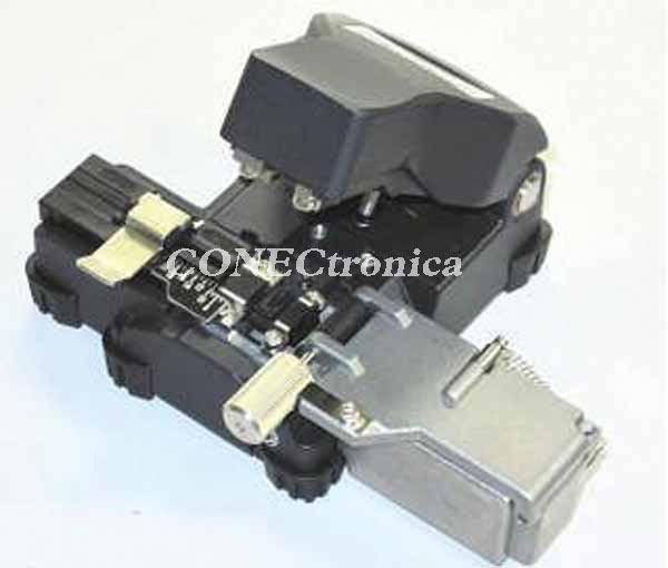

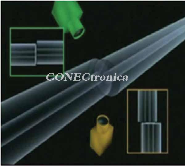
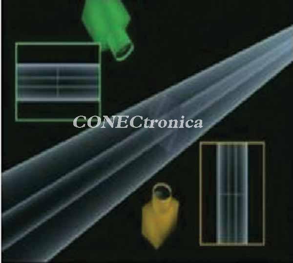
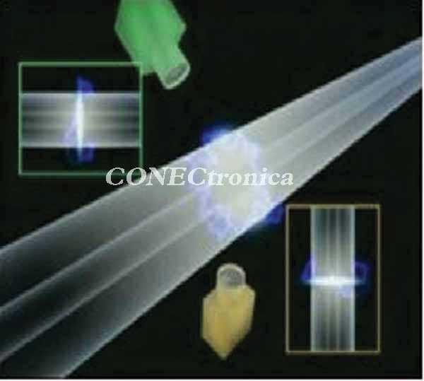
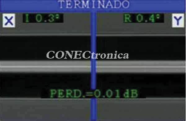
Fusion splicing is performed using a machine commonly called a splicer, fusion splicer, or fusion tool. The machine's main functions include fiber approximation, alignment, fusion, and estimated loss calculation (Figure 2). Finally, the machines have an integrated heater that allows the splice protector to be applied.
How to Perform a Fusion Splicing
: To perform a splice, the fibers must be stripped (the primary coating removed), cleaned with lint-free paper or gauze impregnated with alcohol, preferably ethanol, although isopropyl alcohol can also be used, and finally cut using a precision cleaver that ensures the cutting angle with respect to the perpendicular is less than 1° (Figure 3).
The fibers are placed in the machine, taking care not to contaminate them, and the splice is performed simply by pressing a button, as the machine carries out the process automatically. Once the fusion is complete, the machine evaluates the splice losses, and the splice protector can then be applied.
Fiber alignment is the factor that most influences optical signal loss in fiber optic splices. It can be of three types: longitudinal (separation), lateral, and angular.
Optical signal loss depends on the magnitude of these alignment errors and the characteristics of the fibers being spliced, including core diameters and Numerical Apertures (NA).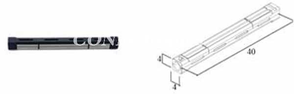 Fusion
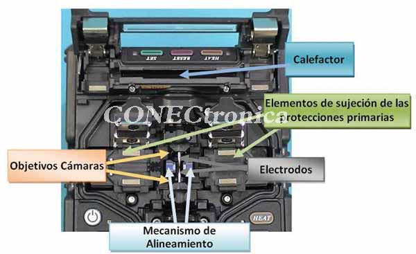
Splicers are composed of different systems, each with distinct functions. These systems can be categorized as follows:
- Primary shielding clamping systems. Their function is to prevent the fibers from moving into or out of the machine and to prevent them from rotating during splicing.
- Splice point viewing system. This allows visualization of the area where the fusion will occur. These systems can consist of a microscope (in older or low-cost machines), a video camera and a mirror, or two video cameras. The latter are the fastest because they allow simultaneous viewing of both alignment axes.
- Alignment System. Its main function is to align the fiber ends so that the cores of both fibers coincide as precisely as possible. There are two main types: core alignment and cladding alignment. The former locates and aligns the fiber cores, and the latter does the same with the cladding.
Machines capable of core alignment use alignment systems such as LID or PAS.
The LID (Light Injection & Detection) system works by injecting light through the cladding into one of the fibers via a bend and detecting the light transferred to the other fiber by extracting the light from the cladding using the same injection method. This system has the disadvantages that the amount of light injected depends on the opacity and thickness of the shielding, so it does not work correctly with some fibers; furthermore, the amount of light injected and extracted is often very weak, which can slow down the alignment.
 The PAS (Profile Alignment System) system aligns fibers by analyzing the profile of their cores in images obtained by one or two cameras when a collimated light source (parallel beams) passes through the fibers. It is the most widely used system because it is the fastest (splices in 9 seconds) and most versatile.
- Fusion System: This system consists of the electrodes and the high-voltage power source. Its purpose is to achieve proper fusion of the fiber material.
- Heating System: This system heats the heat-shrinkable protectors of the splices.
- Control System: This system controls the various components to automate the machine's operation and perform the splice in the shortest possible time and with the highest quality.
The precision and quality of these systems significantly influence the splicing results and the speed of work, resulting in greater profitability.
Types of Fusion Splicers
: There is a wide variety of fusion splicers; They can be divided into two main types: field fusion splicers, the most widely used because they are used in the installation of fiber optic cables, and factory fusion splicers, which are used to perform fiber optic splices in the manufacture of electro-optical elements (amplifiers, compensators, etc.) or research laboratories.
Field fusion splicers allow the joining of multimode fibers: G651, EIA-492 or ISO/IEC 793 and single-mode fibers: G652, G653, G654, G655, G656 and G657.
There are two main types of single-fiber field fusion splicers, which differ in the type of alignment they use to join the fibers: core alignment fusion splicers and cladding alignment fusion splicers.
 Core alignment machines offer the highest quality splices because light travels through the fibers, specifically through the cores. Therefore, aligning the cores minimizes optical signal loss at the splice. For this reason, they are primarily used for splicing single-mode fibers, although they can also splice multimode fibers. Cladding alignment machines are well-suited for splicing multimode fibers, but they can also be used for single-mode fiber splices if the centers of the cores align with the centers of the cladding (low eccentricity levels).
Core alignment fusion splicers consist of two pieces with a V-shaped groove (where the fibers are placed) equipped with lateral and vertical displacement mechanisms.
These machines are more expensive than cladding alignment splicers because they have a greater number of motors and higher-quality cameras and lenses.
Cladding alignment machines have a V-shaped groove on which the fibers to be spliced are placed, aligning the fiber cladding. For some years now, the single-mode fibers used in cables have had very low eccentricity levels. Therefore, cladding alignment machines can also be used to work with single-mode fiber cables less than 15 years old.
Which fusion splicer should you buy?
To select the machine that best suits your needs, you should consider the following:
- Alignment type. Given that core alignment machines offer better characteristics than cladding alignment machines, keep in mind that: for single-mode fibers with minimal losses (telecommunications sector), a core alignment machine is recommended; and for splicing single-mode fibers with reasonable losses (FTTx, CATV, LAN, etc.) or multimode fibers (LAN, industrial control, etc.), any type of fusion splicer can be used.
- Costs. Core alignment machines are more expensive (around 35%) than cladding alignment machines.
- Environmental conditions. It is advisable to select from the different options on the market the machine that can withstand the temperature, humidity, and altitude conditions at which it will be used, as well as being resistant to vibrations during transport, impacts, dirt, etc. For indoor work, the requirements are very basic, but for outdoor work, greater margins are needed.
- After-sales service. The machines are high-precision instruments that require periodic adjustments and quick repairs, so it is advisable to have a good national after-sales technical service.
Mechanical splicing
. A mechanical splice consists of joining the two ends of the fibers in a mechanical support to allow the alignment of the claddings and, through adhesives or pressure systems, preventing fiber separation. Its interior is impregnated with index-equalizing gel to reduce insertion and return losses caused by light reflections resulting from differences in the refractive indices of the fiber core and air.
The mechanical support has a groove that allows for alignment of the fiber cladding and is usually V-shaped, which provides high alignment accuracy.
To use a mechanical splice, the fibers to be joined must have very low eccentricity levels, meaning the center of the core must coincide with the center of the cladding. Otherwise, insertion losses would be very high, especially in single-mode fiber splices.
Due to the tedious, complex, and delicate nature of the assembly, and the importance of the mechanical stability of its components, mechanical splices have been used primarily in testing laboratories, indoor installations, and with multimode fibers.
Technological advancements in recent years have led to the development of easy-to-install, robust, reliable, compact, and affordable mechanical splices.
Fujikura FMSEZ-025/09 mechanical splices are an example of high-quality, compact splices (40 x 4 x 4 mm) that can be installed in splice box trays and allow for splicing single-mode and multimode fibers with 250 µm and 900 µm primary shielding (Figure 6).
They can be assembled in under 3 minutes with minimal tools, which are transported in a small plastic case (Figure 7).
Once assembled, they independently secure the fiber coatings and primary shielding, preventing the fibers from rotating inside.
Features and Installation
The technical characteristics of Fujikura FMSEZ-25/09 mechanical splices are as follows: Coating diameter: 250 µm / 900 µm. Typical insertion loss (averaged):
The following steps are followed to perform the splice:
1. Place the splice in the assembly tool. 2. Open the splice. 3. Place the fiber in the corresponding support with approximately 4 cm of fiber at the end. 4. Strip the fiber. 5. Clean. 6. Cut. 7. Place in the tool. 8. Repeat steps 3 through 7 for the other fiber. 9. Close the splice. 10. Release the fibers and remove the splice. These steps are shown in Figure 8.
Which type of splice is best?
Fusion splices are mainly used with single-mode fiber, and based on technical quality considerations, we can say that fusion splices are the best because they offer lower insertion loss and high return loss (fewer reflections). However, there are other reasons to consider when deciding which type to use, such as economic, technological, and logistical factors.
Regarding economic reasons, it should be noted that mechanical splices require a lower initial investment (1200 to 1500 euros depending on the quality of the tools) than that required for fusion splices (6500 to 10000 euros, depending on the quality and precision of the machine and tools), but the cost of the consumable material for making each mechanical splice (approx. 5 euros) is higher than for fusion splices, since once made it is only necessary to use a heat shrink protector with metal reinforcement whose cost is low (approx. 0.25 euros/unit).
The technological reasons will depend on the type of industry in which the splices are performed. In the telecommunications and CATV network sector, single-mode fibers are used, and where cable lengths are long, splices with low insertion loss are required, making fusion splicing the most suitable. However, for short-distance links (FTTx), both methods can be used. The security sector typically uses multimode fibers and short distances, so both types of splicing can also be used. LAN networks generally use single-mode and multimode fibers over short distances; therefore, either solution is suitable. For the industrial control sector (aerospace, automotive, building control, sensors in hazardous areas, etc.), the fibers are multimode and the distances are very short; therefore, mechanical splicing is also appropriate.
Regarding logistical constraints, it should be noted that the space required for mechanical splicing is less than that needed for fusion splicing, and that while the latter requires energy (although in recent years it has come from batteries), mechanical splicing does not require any type of power supply.
These characteristics make mechanical splices very suitable for carrying out quick repairs, although in some cases these may be temporary.
Author: Pedro Notario, Technical Director TELECOM-UNITRONICS


