

OTDR Testing:
With the rapid advancements in fiber optic technology and new fiber optic network deployments, OTDR testing has become an indispensable method for constructing, certifying, maintaining, and troubleshooting fiber optic systems.
An Optical Time Domain Reflectometer (OTDR) is an instrument used to measure a fiber optic cable run and create a visual representation of it. The measurement data can shed light on the condition and performance of the optical fibers, as well as any passive optical components along the cable run, such as connectors, splices, splitters, and multiplexers.
Once this information is collected, analyzed, and stored, it can be retrieved as needed to evaluate the same cable over time.
Troubleshooting Fiber Optic Cables. The OTDR allows the identification of faults in optical cables (events), determining their location (distance) and characteristics based on total and local signal loss (breaks, excessive bends, defective connectors, etc.).
These devices are available in a variety of formats, depending on the application: portable, laboratory, or rack-mounted, making them suitable for both long-distance installations and local area networks.
How does an OTDR work?
The OTDR sends a pulse of light energy (optical power), generated by a laser diode, to one end of an optical fiber. A photodiode measures the returning light energy, or the optical power reflected and backscattered over time, and converts it into a measurement value that is displayed as a graph (or trace) on a screen. Subsequent analysis of the resulting graphs allows for the study of the cable's condition.
Basic and precise concepts for the correct understanding of this measurement technique
: Attenuation: Reduction of the optical power of the light signal as it is transmitted. The attenuation of a fiber is expressed in decibels per kilometer (dB/km). The degradation of a transmitted light signal can be due to bends, splices, connectors/connections, or the absorption and scattering properties of the optical fiber itself. See VIAVI attenuators.
Backscatter: A term used to describe the scattered reflection of light that returns in the same direction from which it originated. The degree of backscatter is an indicator of the total attenuation of the optical fiber, since the light returning to the source represents a loss in the intensity of the downlink signal. In the case of OTDR testing, for a fiber to be considered in good condition, the amount of backscattered light should be only one millionth of the test pulse.
Reflectance: A measurement of the proportion of light reflected by abrupt changes in material density. Connectors/connections, air gaps, and breaks reflect light, allowing the OTDR to determine the position, condition, and signal loss of these components/elements. The magnitude of a reflection depends on the degree of change in the refractive index.
Refraction: Refraction is the change in direction that occurs in light waves when they pass from one type of material to another. The amount of reflected light is determined by the differences in the refractive index of two fibers and, in most cases, is a problem related to connectors, but it can also be a problem with mechanical splices where an index-equalizing gel is used.
OTDR Testing Process:
Steps to follow for basic configuration, test execution, and report generation:
• Connect equipment and perform operational checks
• Clean connectors, fiber ends, and adapters
• Connect launch cables
• Select test configuration based on network type and conditions: Range, pulse width, acquisition time, refractive index, event thresholds.
• Start data acquisition (trace)
• Store or upload results
• Carefully disconnect cables, connectors, and adapters
Recommended practices for OTDR use:
Careful and correct methodology for cleaning all elements and checking that they are compatible with each other.
Use of launch and receive cables:
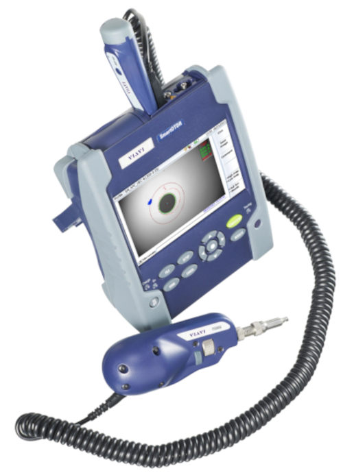
The best handheld OTDR tools offer touch-and-click operation and applications tailored to different skill levels and network types. The VIAVI SmartOTDR delivers improved productivity with automated pass/fail results.
Interpreting OTDR Test Results:
Once the OTDR tests are complete, the instrument displays the results in both numerical and graphical formats. The graph, also called a trace, shows the location of each connector, connection, splice, bend, or break, along with the signal loss (in dB) and reflection characteristics of each element. Depending on the equipment, it can be presented as a line graph or using icons, with pass/fail information based on the entered thresholds.
Correctly defining the specifications will allow us to choose the appropriate OTDR.
• Dynamic range: expressed in dB, it determines the maximum observable length of a fiber.
• Event dead zone (EDZ) and attenuation dead zone (ADZ): The minimum distance between or after an event that is observable.
• Wavelengths: 850 nm and 1300 nm for MM and 1310 nm, 1550 nm, and 1625 nm for SM
Calibration of OTDR Measurement Equipment:
In sectors where the accuracy of OTDR test results is essential, the IEC 61746 calibration standard and the TIA/EIA-455-226 standard (adopted from the IEC standard) are recognized.
The IEC standard includes specific practices for calibrating point-to-point accuracy, linearity, attenuation, power output, and delay. Given the complexity of OTDR calibration, it is best to leave this task to the equipment manufacturers or certified calibration laboratories.
The Future of OTDR Testing:
Without technology like OTDR testing, advanced fiber optic applications would not be viable. The ability to “see” inside thousands of optical fibers no thicker than a human hair is not only an incredible achievement but has also become a practical necessity.
In the coming decade, new 5G networks with massive data loads, smart cities connected through communication networks, and the continued deployment of FTTH services will increase the industry's demand for efficient and versatile OTDR testing.
With revolutionary OTDR advancements like SmartLink Mapper and Smart Acquisition, which make testing simpler, more accurate, and more powerful, VIAVI addresses the future of fiber optic installation and maintenance needs.
For more information on new solutions for fiber optic installers, contact the experts at
VIAVI technical document at this link

