This article explains how efficient connectorization technology can be at different points in the access network, providing accessibility, flexibility, and regulatory compliance while taking into account optical balance constraints. With the latest developments in active components that increase optical balance, operators can much more easily adopt connectorization strategies that ensure network scalability—in terms of bandwidth, distance, or broadcast—and achieve minimal operating expenses (OpEx).
 Telecoms in Europe are under constant pressure to increase the bandwidth they offer. This bandwidth is increasing by 50% year after year, and the residential broadband penetration rate has risen by almost 20% in the last five years. Broadband services are catalysts for the economy, significantly reducing telecommunications costs for businesses, stimulating growth, particularly in rural or economically depressed areas, and boosting both public and private companies.
Fiber to the Home (FTTH/B) networks are the foundation of these future broadband networks. Their transmission capacity is virtually unlimited and unrestricted compared to traditional copper systems. The number of homes passed with FTTH/B networks is growing exponentially, reaching over 5.5 million homes in the first half of 2009 (a 15% increase over the previous six months). In this first half of the year, 120 new FTTH/B projects were added, bringing the current total to 233.
Despite steady progress, the 2 million subscribers in Europe still represent a small number compared to the 6 million in North America or the 30 million in Asia-Pacific. Recognizing this lag, the European Commission has embarked on numerous initiatives to stimulate the FTTH/B market – including its recommendation for the regulation of access to Next Generation Networks and the establishment of the European framework for the Information Society. At the same time, national governments are establishing Open Access topologies while ensuring the availability of the necessary resources to provide universal access.
Network Topologies, Standards, and Service Strategies:
With millions of euros invested in FTTH/B, deployment and penetration strategies must be designed to save operators time and money—during construction and later, during activation and operation. The two most common topologies used in FTTH/B networks deployed today are Point-to-Multipoint (P2MP) and Point-to-Point (P2P), the latter typically used for Ethernet transmission. Point-to-Multipoint networks utilize optical splitters in the field.
Currently, the GPON point-to-multipoint topology is predominant in Europe and is an evolution of the BPON standard. GPON supports high speeds, offers improved security, and allows complete freedom of choice of Layer 2 protocol (e.g., ATM, GEM, Ethernet).
The advantages of a PON topology are that a single OLT (Optical Line Termination, the central office equipment) can be used to connect multiple ONTs (Optical Network Terminals, the subscriber equipment) via optical splitters placed between the central office and the subscriber. Currently, the preferred splitter ratios are 1:2 and 1:4 at the central office, and 1:8 or 1:16 in the outside plant. Since OLTs (deployed in central offices) are expensive and consume a lot of power, PON architectures with intermediate splitters create considerable cost savings by eliminating much of the need for active equipment.
 The Need for Connectivity:
Most operators began by deploying P2P topologies with the goal of delivering maximum bandwidth to the subscriber. However, this strategy has proven very expensive, given that it requires installing an entire fiber optic cable, point-to-point from the central office, and it's not just the fiber itself, but fundamentally all the associated cabling. This topology would only be efficient in very high-density environments. In general, deployment environments can be divided into four categories:
- High-density urban areas.
- Low-density urban areas.
- Rural areas.
- Industrial areas with mixed topologies.
For low-density environments, PON architecture is ideal, as it results in a much more economical deployment. It basically consists of optically splitting the signal using an optical splitter, allowing multiple subscribers to be served from a single fiber in the central office. This model has some limitations:
- Lower bandwidth for subscribers (depending on the level of splitting).
- The use of optical splitters implies greater attenuation, and therefore more attention must be paid to network design, including how and where to use connectors and/or splices.
- Network expansion can be costly if easy reconfiguration has not been planned from the outset.
The choice of topology has been and will continue to be a subject of ongoing debate. Operators can, however, deploy point-to-point topologies and simultaneously overlay PON topologies on top of them. Regardless of the physical cable path, the topologies are logically implemented through the use of:
- Splices - in which two fibers are permanently joined using a fusion splicer.
- Connectors – which are made in the factory, adding standard terminations to the bare fiber ends that provide mechanical protection and ease of operation.
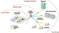
Connectorization was originally developed for installation in central offices and has subsequently been introduced into outside plant applications, especially with FTTH applications in recent times. Thus, connectorization can be used at any of the three strategic points in an FTTH network:
- Central Office – the building where the active equipment (switches, DSLAMs, etc.) is located along with the main cable distribution frames.
- Outside Plant – cabinets, termination and splice boxes, etc.
- Customer – whether residential or business.
The level of splicing or connectorization used in an FTTH/B deployment depends heavily on each operator's requirements. The type of deployment (new neighborhoods or over an existing network), the demographic environment (high- or low-density areas), the regulatory environment, along with the project's CAPEX and OPEX limits and balance, are the main factors influencing this decision. Essentially, it's a matter of whether to use, and to what extent, a spliced or connectorized optical splitter approach at different points in the network.
For many carriers, building a network based on fiber splicing was easy, especially initially. However, carriers have had to reassess this initial strategy, given that splicing offers significant competitive advantages in terms of optimizing resources, both in network construction initially and later in its operation, while also ensuring greater network flexibility and reliability. Without splicing, the operator has to lay each fiber end-to-end from the central office to each customer.
In highly regulated environments, this might not seem so problematic. In more typical, less regulated environments, the problem is significant and can result in a network utilization efficiency level of only 20%, when it should be at least 80%.
The new FTTH/B networks are ushering in a new era of regulation for communications networks in all major European countries. These regulations stipulate that the spliced connection cannot be terminated at the customer's premises, as this could hinder switching providers. This connectivity requirement is reflected in the policies of the European Commission, which stipulates the requirement of "easy access".
Optical Balance Considerations:
Given that fiber has only begun replacing copper in the last mile in the last decade, it's not surprising that the initial trend of extensive splicing was slow to change. Operators viewed splicing as a cheaper technique in terms of upfront cost (no need to purchase connectors, and especially no need to purchase the space-constrained components that could house them), and they were also concerned about optical balance and potential new points of failure in the network. Furthermore, they were unconvinced of the need for both flexibility and easy network monitoring. This initial trend has now completely reversed, and operators are altering their deployment topologies, maximizing connectorization from the central office to the subscriber, with optical balance as the sole limitation.
From a pragmatic standpoint, connectorization clearly offers maximum flexibility in the fiber network and is the best way to guarantee its future growth, both in terms of customer penetration and changes in bandwidth demand. However, it is also clear that connectorization has limitations and disadvantages compared to splicing, which results in higher attenuation.
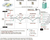 Thus, optical balance, that is, the maximum possible signal attenuation between the central office equipment and the subscriber equipment, has become one of the key parameters in the design and construction of FTTH/B networks. The typical value for this optical balance is between 20 dB and 30 dB (and is usually designed for 26 dB).
Factors Affecting Optical Balance
In a fiber optic network, there are two types of losses that impact optical balance:
- Attenuation – which affects signal quality by decreasing its power level.
- Return loss – which affects signal quality by increasing noise. Recommended return loss is less than 32 dB (ITU recommendation), calculated as the sum of all light reflections back to the source, the laser.
There are several points to consider:
Laser Output Power:
Continuous developments in higher-power lasers and improved receivers continue to expand the optical balance (C+ lasers versus B+ lasers, etc.). In the medium and long term, this will contribute to improved network quality and flexibility, increasing the possibility of placing passive components within the network (connectors, optical splitters, etc.) without compromising the BER. In the short term, this laser output value definitively determines the network's range and the split ratio.
Typical OLT-ONT Distance:
The optical balance considers the total distance of the segment between the OLT and ONT. This distance linearly influences the attenuation (called spectral attenuation) introduced by the fiber optic cable (typically considered to be 0.4 dB/km at 1310 nm, which is the most restrictive wavelength for design purposes). Other elements along this path between the OLT and ONT introduce losses, such as:
- Connectors.
- Fusion splices.
- Optical splitters.
Knowing the number of connectors, fusion splices, and optical splitters, as well as the spectral attenuation of the cable and the characteristics of the active equipment, the maximum permissible distance can be calculated. For example, the maximum distance for a GPON network with a 1:32 optical splitter and a maximum optical balance of 28 dB is 20 km.
In reality, the distances to users in an FTTH network are usually between 5 km and 20 km.
Connector Losses:
A connector generally produces two main types of losses:
- Insertion loss – This depends directly on the connector type and wavelength. It's important to note that an FTTH network uses three different wavelengths simultaneously (1310 MHz from user to central office, 1490 MHz from central office to user, and 1550 MHz from central office to ONT for the video signal). Typical connector losses are 0.3 dB, and in the worst case, 0.5 dB.
- Return loss – Since connectors are typically fiber-to-air-to-fiber contacts, a small amount of light is reflected back to the source during these transitions. By using APC connectors (angled 8° on the connector face), return loss can be minimized at each transition, even falling below 65 dB.
It is impossible to build a passive fiber optic network without connectors (equipment uses them, central office jumpers have them at both ends, etc.). Any network installation is certified and tested, generally using OTDR equipment (reflectometers), which allows installers to detect fusion failures, dirty connections, poor fusion quality, etc.
Optical Splitter Losses:
Like any passive component, optical splitters introduce:
- Insertion losses – these depend primarily on the splitter's ratio and quality. For example, a 1:2 optical splitter typically loses 3.5 dB.
- Return (reflection) losses – an individual optical splitter typically has a reflection loss of 50-55 dB, which is a considerable value that impacts the overall reflection result much more than connectors.
- Directivity – this is the ratio of power diverted from the input of an optical splitter to other inputs of that same splitter, and it affects the overall signal in the same way as the normal reflections discussed in the previous point.
Fusion Splice Losses:
Typically, fusion splice losses are almost negligible, on the order of 0.1 dB per splice. However, mechanical splices require close monitoring of the resulting values, which are highly dependent on the technology used.
European operators are moving towards connectorization.
Operational, commercial, and optical balance considerations have led major European operators to massively adopt technologies that promote connectorization in their FTTH deployment strategies.
One leading European operator, for example, began deploying a fusion-based topology because it was familiar with the technology and was not permitted to install cabinets in the street (requiring underground solutions). Initially, it was also concerned about the impact of numerous connectors on the overall optical balance of its network.
As its network deployment progressed, the lack of flexibility became increasingly apparent. When it was necessary to operate on the inputs or outputs of optical splitters, verification tests could not be performed without cutting the active fibers and interrupting service to customers. Even more significant were the problems with the new customer activation process, which made it very slow and expensive. Furthermore, during the deployment, the regulator mandated open solutions that allow for shared connections to the subscriber and avoid multiple verticals.
Designing for Growth and Flexibility:
In contrast, another European Telco operator has massively deployed a GPON-based P2P network with a 1:64 split level. This network predominantly uses connectorization. At the Remote Node (street distributor), a full cross-connection is used between the cable from the central office and the distribution cables running to the end subscribers, allowing for immediate activation and migrating P2P service customers to PON in a matter of minutes. The operator uses a total of five connectorized connections and one fusion splice per user up to this intermediate distributor.
The operator uses terminal boxes within the buildings that are terminated with connectors. Depending on whether a direct interconnection topology with the customer cable or a cross-connection with a neutral box is used, one or two additional pairs of connectors are required.
In the entire network, up to the ONT, there can be a total of 10 pairs of connectors and 4 splices. This represents up to 3.4 dB of loss (maximum of 5.4 dB in the worst case).
Assuming that the optical splitters (one or two cascaded to achieve a 1:32 ratio) lose 18 dB, the total worst-case loss would be 23.4 dB, providing a protection margin of approximately 2 dB up to the 26 dB used as the design limit.
By introducing connectors and maximizing the use of the entire optical balance, a very high level of network flexibility was achieved. This basically means that with minimal OpEx expenditure, network growth can be guaranteed, meaning that either more bandwidth can be provided to end customers, more customers can be covered, or they can be located further away.
Architectures that make extensive and intelligent use of connectors throughout the network, from the central office to the customer, enable the network to be monitored and maintained, and allow for flexible and non-traumatic changes and expansions:
- Operational tasks are reduced.
- Operators can align their investment with service demand and their penetration level.
- Preventive and corrective maintenance, integration of new active equipment, etc., can be performed in minutes with a pre-connectorized solution, significantly reducing time and costs.
- In multi-family building locations, pre-connectorized solutions significantly reduce the amount of equipment, the number of splices, the number of technicians required, and streamline the activation process considerably.
Author: José Luis González - Technical Director ADC KRONE, Iberia