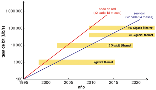
 The dramatic increase in network bandwidth requirements, driven largely by the Internet (Web 2.0) and video-on-demand applications (IPTV), is prompting the continuous upgrade of service provider routers with new 10G interfaces. In fact, 40 Gb/s interfaces are already being deployed, and some long-distance DWDM routers already carry 40G channels. However, the need for 100 Gigabit Ethernet (100GbE) is becoming increasingly evident (Figure 1). The 100 Gb/s rate represents the natural extension of the Ethernet hierarchy (10M/100M/1G
/10G) that has been so successful over the past few decades. While some believe that 100GbE is arriving late, these are those who have been working with vendors that have proprietary 100 Gb/s solutions and believe that the 100GbE standards should have been finalized much earlier. The two main standardization bodies involved in these tasks are the IEEE (802.3 Higher Speed Study Group, HSSG) and the International Telecommunication Union (ITU-T). However, several alliances and associations have also been involved in the 100GbE standard specification process, including the Alliance for Telecommunication Industry Solutions (ATIS), the Optical Internetworking Forum (OIF), the Ethernet Alliance, the Road to 100G Alliance, and the Optoelectronics Industry Development Association (OIDA). One of the most critical aspects of the standardization process is defining the 40GbE specification. As is well known, today's highest-capacity routers are developed with 40 Gb/s ports, and compatibility is needed between Gigabit Ethernet and the SONET/SDH hierarchy, whose standardized bit rates are defined using multiples of four. This is arguably one of the biggest points of contention today, compounded by the fact that while Gigabit Ethernet is indeed capable of handling asynchronous traffic, SONET/SDH is not the most efficient way to manage the current volume of IP traffic. In this article, we will discuss the standardization initiatives currently underway regarding 100GbE, while also introducing some of the technologies that will be used in the implementation of the first commercial devices.
Standardization Activities:
The IEEE 802.3 HSSG group has actively participated in defining the MAC layer parameters and the physical LAN interface specifications of the 100GbE standard. This standardization process is key to ensuring the correct interconnection of Ethernet equipment in enterprises and data centers with WAN transport systems. The Optical Transport Network (OTN) is the future platform for exchanging all types of digital information. The ITU-T has standardized the OTN through the G series of recommendations: frame structures (G.709), architectures (G.872), and management functions (G.798). Specifically, it consists of a multiplexed hierarchy of optical data units (ODUs) organized within optical transport units (OTUs), which form the basis of GFP-Framed or GFP-Transparent data services. OTU containers are numbered from 1 to 4 and correspond to the following bit rates:
1 – OTU1/ODU1: 2.5 Gb/s
2 – OTU2/ODU2: 10 Gb/s
3 – OTU3/ODU3: 40 Gb/s
4 – OTU4/ODU4: 120 Gb/s
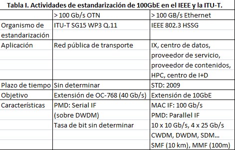 The development of the OTU4 container specification is currently underway in the ITU-T SG 15 working group and constitutes the 100 Gb/s reference model in the IEEE HSSG group. OTU4 containers will be able to transparently carry nine 10GbE signals or a single 100GbE signal. Complementary IEEE and ITU-T activities related to the 100GbE standard are summarized in Table I.
Figure 2 schematically shows a 100GbE MAC architecture model, called 100GE, with 10 physical 10G encoding I/O sublayers for 10 km of single-mode fiber (SMF). The challenge in standardizing these types of applications is to develop first-generation transceivers using current technology and then subsequently improve cost, power, and size as new technological possibilities emerge. In any case, the choice of operating wavelengths must be in accordance with both current and future technologies.
100GbE Technologies
When analyzing the optoelectronic technology of 100GbE systems, we can differentiate between two types of applications. The first refers to 100 Gb/s LAN networks over SMF, while the second corresponds to the case of multimode fiber (MMF). In both cases, we can speak of two technological generations: the current technology and the technology that will be necessary in 8 or 10 years.
100 Gb/s SMF LAN systems can be implemented using various alternatives: existing 10G LAN NRZ technology over WDM channels, advanced modulations over a single optical carrier and dispersion compensation techniques, or new NRZ technologies at 25 Gb/s over WDM channels. In all cases, this applies to both 1310 nm and 1550 nm wavelengths. The 10GBASE-ER specification supports 40 km at 1550 nm, which equates to approximately 8 dB losses in the power balance, compared to 16 dB at 1310 nm. In contrast, 10GBASE-LR supports 10 km at 1310 nm, which equates to approximately 4 dB losses. The higher losses at 1310 nm are offset by the fact that no dispersion compensation is needed, so direct modulation lasers can be used. The 100 Gb/s bit rate is formed from ten 10 Gb/s WDM channels, hence the common name 10x10G. Any of the aforementioned 10GBASE technologies can be used to implement these types of systems. For example, CyOptics and Cray have developed a 1550 nm transceiver using the 20 nm CWDM window.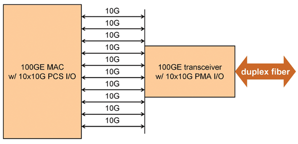 As mentioned earlier, another alternative is the use of advanced optical modulation schemes such as QPDSK or DQPSK (CONECtrónica, number 114, pp. 8-12, February 2008). In this case, the symbol rate is halved, resulting in two 50 Gb/s channels that can be placed within a single DWDM channel. Additionally, by using orthogonal polarizations, a further reduction in the symbol rate can be achieved, obtaining four orthogonal 25 Gb/s channels.
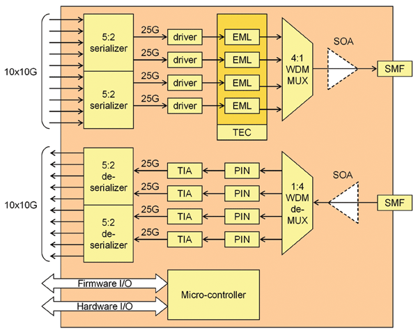 Finally, the third alternative is WDM multiplexing of four 25 Gb/s NRZ signals (4x25G). This option is particularly attractive because characteristics such as cost, power consumption, size, and reliability improve with the reduction in the number of channels, thus offering advantages over the 10x10G option. The scheme is quite similar to the 10GBASE-LX4 standard, although in this case for SMF fibers. The block diagram of the 4x25G transceiver architecture is shown in Figure 3. The connection to the electrical interface is made using 10 Gb/s signals, typical input/output rates of the main CMOS technologies used for the MAC layer.
'
 Conversions from 10 Gbps to 25 Gbps and vice versa are achieved using 10:4 serializer circuits. During transmission, the signals are modulated using four lasers with electroabsorption modulators (EML), which generate four different wavelengths that are multiplexed onto the same fiber. For distances under 4 km, either the second or third window can be used. It is also possible to use four lasers with direct modulation, but in this case, dispersion compensation techniques are required at 1550 nm. During reception, the reverse process is performed: the four WDM optical channels are demultiplexed and photodetected by separate receivers consisting of a PIN photodiode and a transimpedance amplifier (TIA). The WDM channel spacings support various possibilities, which are listed below: IEEE LX-4 25 nm grid, ITU G.694.2 20 nm CWDM grid, or ITU G.694.1 400 to 800 GHz (2 to 4 nm) DWDM grids. The first two allow the use of lasers without temperature control.
Finally, it should be noted that since power losses are greater at 1310 nm, semiconductor optical amplifiers (SOAs) are required for metropolitan area networks (ranges under 40 km). These can also be replaced by high-power lasers for transmission and avalanche photodetectors (APDs) for reception. At 1550 nm, the dispersion control techniques typically used are: pre-chirping
in the transmitters, compensating fibers, or electronic dispersion compensation (EDC) circuits.
100 Gb/s MMF LAN applications are primarily focused on internal connections between racks over distances under 100 m. These multimode fiber links are usually built using VCSEL lasers at 850 nm (CONECtrónica issue 91, pp. 8-10, October 2005). VCSEL technology works relatively well up to 10 Gb/s, but at higher speeds, high bias currents are required, which significantly degrade the device's lifespan. Therefore, the only option in this case is to use a 10x10G scheme to generate the 100 Gb/s signal. Similar to the 10GBASE-SR standard, it is proposed to use OM3 multimode fiber, which has a nominal bandwidth of 2000 MHz/km at 850 nm, such that over 100 m, the dispersion of a 10 Gb/s NRZ signal is minimal. In contrast, older fiber types, such as the OM1 type defined in the 10GBASE-LRM specification, are not suitable.
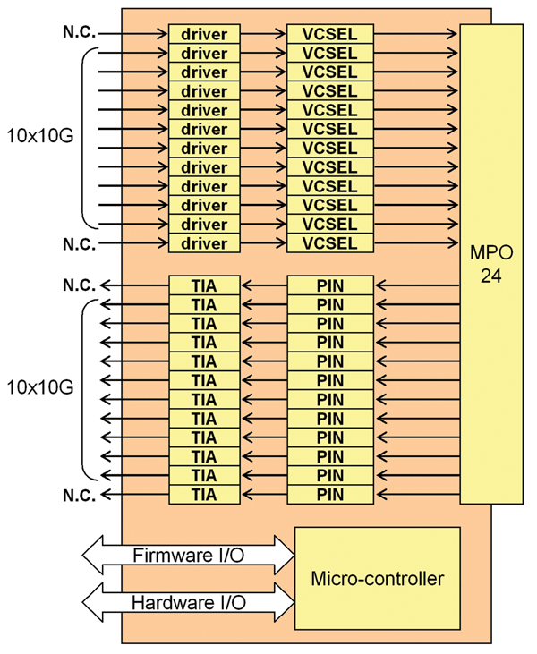
Figure 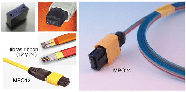 4 shows the architecture of a 10x10G MMF transceiver. The electrical input/output interface handles 10 Gb/s signals, as with SMF transceivers, so they can be easily interchanged. The architecture actually includes 12 channels, allowing it to support applications beyond 100GbE, such as InfiniBand. A 24-fiber MPO connector (12 for transmit and 12 for receive) is used for the optical interface, which can also be replaced by two separate 12-fiber MPO connectors. The 24 fibers must be carefully aligned with the VCSEL transmitters and PIN photodiodes, similar to the process used with POP4 and QSFP transceivers. This is typically more complex and expensive than aligning 12 fibers separately (similar to SNAP12 modules), although it achieves higher density and simpler cable management. Figure 5 shows photographs of the two types of MPO connectors.
All these technologies just presented are the ones that will come into play in the development of the first commercial products based on the 100GbE standard. However, over time, it is expected that all of this will evolve, and in about 8-10 years, second-generation devices will be available, where key aspects such as the large-scale manufacturing of PICs (photonic integrated circuits), the use of 4-channel buses, short-range copper interconnects, DP-QPSK optical modulation, and 25 Gb/s VCSELs will be the driving forces of change. There is even talk of 10 Terabit Ethernet, for which we will obviously have to wait a few more years.
Francisco Ramos Pascual. PhD in Telecommunications Engineering.
Full Professor at the Polytechnic University of Valencia.