
Recent advances in technologies such as WDM and TDM have boosted the deployment of high-speed optical networks in MAN and WAN environments. However, local area networks (LANs) are characterized by a series of requirements that cannot be easily met by WDM and TDM. Furthermore, WDM and TDM systems impose the use of protocols and hardware at distribution nodes that add complexity and unnecessarily increase the cost of the LAN. In a TDMA access system, the total traffic volume is limited by the product of the number of users and their respective transmission rates, since only one user can transmit at any given time. For example, if 100 users want to transmit at 1 Gbit/s, equipment capable of supporting a capacity of 100 Gbit/s would be needed. Additionally, TDMA systems exhibit significant latency, given the extensive coordination required from the central node to allocate transmission slots to each user. Unlike TDMA, a WDMA access system allows each user to transmit at the maximum rate of the network hardware, since each channel is transmitted over a reserved wavelength. A WDMA system can easily support a capacity of 1 Tbit/s, but unfortunately, it is difficult to build a WDMA system for a dynamic user group. In this case, the control channels and collision detection schemes would require a significant amount of bandwidth.
Fortunately, there is an alternative to TDMA and WDMA access schemes: OCDMA (optical code-division multiple access) systems, which do not require any type of time or frequency management system. OCDMA operates asynchronously, without centralized control, and packet collisions do not occur. As a result, OCDMA systems are characterized by lower latencies than TDMA or WDMA. Additionally, since time slots and frequencies (wavelengths) do not need to be individually assigned to each user, multiplexing results in improved performance. Ultimately, OCDMA systems are the best option for deploying high-speed optical local area networks. This article will describe the basic principles of OCDMA systems and present some architectures for their practical implementation.
Orthogonal codes
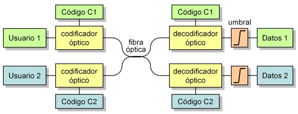
The operation of an OCDMA system is typically based on the use of spread spectrum techniques and orthogonal codes, which allow for the differentiation of data signals from each user on the network. Essentially, OCDMA is similar to the CDMA scheme used in radio frequency, with the key difference being the use of special codes. Undoubtedly, the properties of these codes determine the characteristics and performance of the network. The system diagram is shown in Figure 1 for the specific case of two users. As can be seen, each user employs a different code to encode the signals to be transmitted. These signals are then combined and transmitted over the same medium (fiber optic cable). At the receiving end, the received signals are differentiated using correlation-based decoders, each adapted to the code of a specific user.
An orthogonal code is a family of data sequences with good autocorrelation and cross-correlation properties. These are defined to obtain a maximum level of autocorrelation (user code, useful signal) and a minimum level of cross-correlation (other users' codes, interference). Let's consider two codes represented by C1 = {0, 1, 4} (mod 13) and C2 = {0, 2, 7} (mod 13), that is, two sequences of (0, 1) chips of length 13, where there are 3 chips set to "1" in the indicated positions. These codes and their correlation functions are shown in Figure 2. It can be seen that the autocorrelation provides a maximum output level of amplitude 3, while the cross-correlation of both codes always provides values of amplitude 1 at most. It is therefore simple to discriminate between them by simply placing a threshold detector set to an amplitude of 2. In this way, in the transmitter, each bit of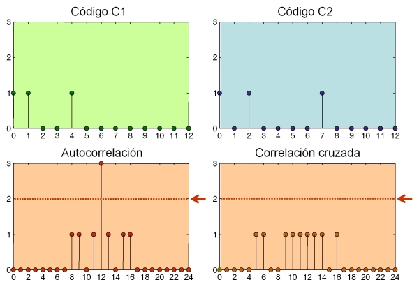 information is encoded with a frame of 13 chips with the corresponding code (C1 or C2). In this case, in User 1's transmitter, a "1" bit is encoded with the sequence {0, 1, 4} (mod 13), where each chip set to "1" represents an optical pulse, while a "0" bit is encoded with the absence of optical pulses. At the receiver, the correlation of the input sequence with the respective codes will produce optical pulses below the threshold, except in the case where a "1" bit has been transmitted and coincides with the code used, resulting in an optical pulse that exceeds the threshold. This allows each receiver to be tuned to the code to receive the data signals of a specific user, preventing the signal transmitted by another user from causing interference. The process can be extended similarly for more than two users. Table I lists a whole series of optimal orthogonal codes.
| Length | Codes |
| 7 | {0,1,3} |
| 13 | {0,1,4}, {0,2,7} |
| 19 | {0,1,5}, {0,2,8}, {0,3,10} |
| 25 | {0,1,6}, {0,2,9}, {0,3,11}, {0,4,13} |
| 31 | {0,1,7}, {0,2,11}, {0,3,15}, {0,4,14}, {0,5,13} |
| 37 | {0,1,11}, {0,2,9}, {0,3,17}, {0,4,12}, {0,5,18}, {0,6,12} |
| 43 | {0,1,19}, {0,2,22}, {0,3,15}, {0,4,13}, {0,5,16}, {0,6,14}, {0,7,17} |
Table I: Optimal codes of different lengths.
'
Optical generation and detection of OCDMA signals
To date, numerous architectures and techniques have been proposed for generating OCDMA signals. Our aim is not to perform an exhaustive analysis of them, but rather to explain the fundamentals of one of the most common ones.
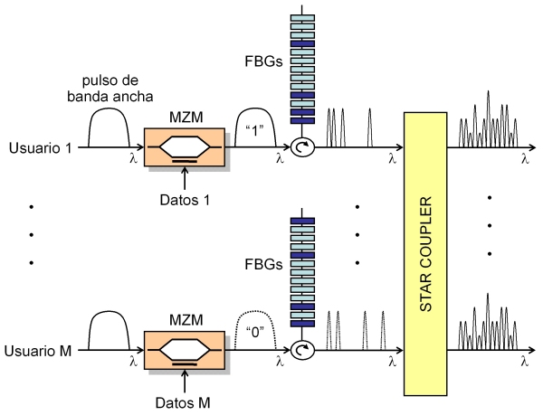
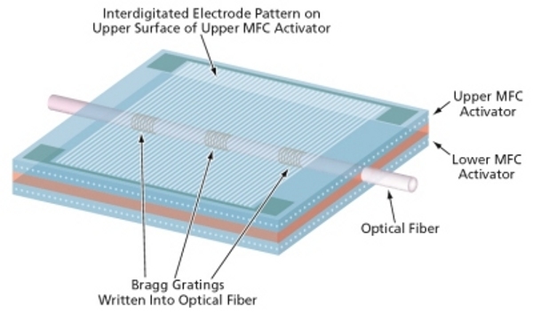
Unfortunately, techniques based on coherent light sources for generating ultrashort pulses are quite expensive and not competitive in the market. Therefore, since M. Kaevhrad proposed a non-coherent OCDMA system in 1995, non-coherent spectral amplitude coding technology has garnered significant interest. This is further fueled by the fact that fiber Bragg gratings (FBGs) are the ideal device for this type of signal processing. In this case, the FBGs act as optical filters that selectively (spectrum slicing) reflect spectral portions of a wide-bandwidth, incoherent optical pulse. The transmitter for this technique is schematically represented in Figure 3. Each user emits a wideband pulse with the information to be transmitted ("1" or "0"), which is directed towards an FBG-based encoder printed with the user's code. This code indicates which wavelengths of the spectrum will be reflected and, therefore, transmitted through the fiber. For a code of length N, encoders composed of N cascaded FBGs are required, which in turn will produce a sequence of N chips centered on wavelengths (l1, l2, ..., lN). In this example, a sequence of N = 13 chips is used, with 4 of them active. The wavelength of each FBG can be adjusted using piezoelectric devices (Figure 4), which are what actually configure the code. Subsequently, a star coupler is connected to the output of each encoder, injecting the signals into the local area network's optical fiber. As can be seen, the resulting signal is equal to the sum of all the generated signals, making it difficult to visually distinguish the data transmitted by each user.
'
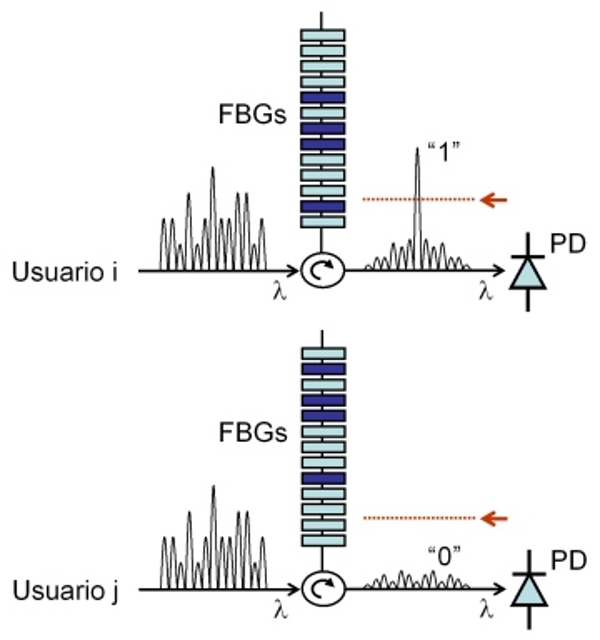 At the receiver (Figure 5), the decoding process is very similar, where the FBGs are now tuned to a specific code. A large-amplitude pulse is obtained at their output if the code matches (autocorrelation) and a "1" has been transmitted, and several smaller-amplitude pulses are obtained in the case of data signals from other users (cross-correlation). Clearly, the performance of the technique will depend on the total number of users, M, and the length of the codes, N. In general, the error rate will increase with M, requiring larger values of N as M increases.
'
Source: www.radioptica.com

