This new application will be discussed in subsequent versions of this document.
The document's agenda is presented below:
- IEEE 802.3bj – 100GBASE-CR4
- IEEE 802.3bp - Gigabit Ethernet over a single pair
- IEEE 802.3bm - 100GBASE-SR4
- IEEE 802.3bq – 40GBASE-T
- IEEE 802.3bt – Power over Ethernet (PoE)
- ANSI/TIA 568-C 2.1 - Twisted Pair Cabling for 40Gbps
- ANSI/TIA 568-0.D - Telecommunications Cabling for Enterprise Environments: General Aspects
- ANSI/TIA 942-A - Data Centers
- ANSI/TIA 4699 - Structured Cabling for Educational Environments
- ANSI/TIA TSB 162-A - Wi-Fi Cabling
IEEE 802.3bj – 100GBASE-CR4
This standard aims to achieve 100 Gigabit/s transmission speeds while respecting the Ethernet frame format defined in 802.3, but using either Backplane (a stack of switches) or twin-axial cables, with lengths up to 5 meters, as transmission media.
This protocol uses four parallel transmission channels, with a transmission rate of 25 Gbps per channel in full-duplex mode.
The project includes four possible connection formats. 100GBASE-KR4 is designed for connecting next-generation switches or blades (backplanes), 100GBASE-PR4 is designed to interconnect conventional switches and enable stacking with switches that implement new stacking systems, and finally, the 100GBASE-CR4 protocol is designed to connect Top-of-Rack (ToR) switches to servers using twin-axial cables up to 5 meters long.
The estimated release date for the standard is July 2014.
IEEE 802.3bp - Gigabit Ethernet over a Single Pair.
Following the Call for Interest (CFI), which could be described as an industry survey to assess the need for a Gigabit Ethernet application over a single twisted pair, launched in early 2012, the project has finally moved forward and has been renamed IEEE 802.3bp.
The primary application environment for this new standard would be the industrial sector, specifically the automotive, aviation, and rail industries, where this application would serve to connect diagnostic systems, internet access, control systems, cameras, etc. Although the CFI establishes the aforementioned sectors as the primary application environment, it is obvious that it would be applicable in any other environment where the performance of the installed cabling supports the requirements of this standard, which is still being defined.
It is important to mention that this standard recommends the use of UTP cables, given their superior performance compared to shielded cables in environments where grounding is not available.
In parallel, but separately, a PoE standard using only one pair is also being developed. This standard will be implemented on the interfaces used in this application, allowing remote devices to be powered using just one copper pair.
Work is underway on interfaces that enable links of approximately 15 meters in length and up to four connections, primarily for automotive applications. Additionally, other interfaces are being developed that will extend this distance to over 40 meters, enabling applications in industrial, rail, and aviation sectors.
IEEE 802.3bm – 100GBASE-SR4
The IEEE 802.3bm project was created to develop the 100GBASE-SR4 application, which consists of 100Gbps transmission using eight multimode fibers, four in each direction, modulating each fiber at a wavelength of 25Gbps, instead of the 20 fibers at 10Gbps per fiber used by the current 100GBASE-SR10 standard. The reason for this new development is purely economic, since the necessary passive fiber optic infrastructure is much simpler and, above all, the optical interfaces are expected to be up to 50% cheaper than the current 100GBASE-SR10. Furthermore, to achieve this significant cost savings in optical interfaces, several modulation techniques are being considered, although no consensus has yet been reached. The different modulation proposals are shown in the following figure, representing in each case the percentage of support received for each of them in the different meetings held to date.
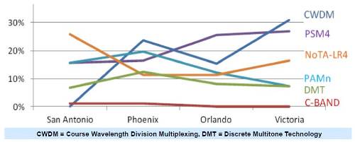 As can be seen, the most voted option is CWDM, although at the moment it has support barely exceeding 30%, and to make the final decision, support must reach at least 75%. Initial indications regarding the maximum supported distances for this application over multimode fiber suggest that around 70 meters can be achieved with OM3 multimode fiber and approximately 100 meters with OM4 multimode fiber, considering up to two hops or connections in both cases. The same project is also working on the 40GBASE-ER application, to achieve 40Gbps transmissions over single-mode fiber at distances of 40 km. The standard is expected to be published by March 2015.
IEEE 802.3bq – 40GBASE-T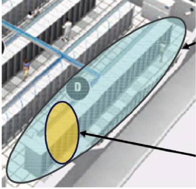 The working group responsible for developing the 40GBASE-T application, which enables 40Gbps over twisted-pair cabling, has finally been established. This working group, and ultimately the official name of the 40GBASE-T standard, is IEEE 802.3bq. In addition to maintaining Ethernet frame formats, this application also includes auto-negotiation, meaning it will be backward compatible with existing Ethernet applications such as 10GBASE-T and 1000BASE-T. A maximum length of 30 meters has been established for 40GBASE-T channels, with up to two connections. This should be sufficient to cover the maximum length of a row of racks within a data center, the primary objective of this new protocol.
To define the required characteristics of 40GBASE-T interfaces, 5-meter channel models (two 1-meter patch cords and one 3-meter link) and 30-meter models (two 3-meter patch cords and 24-meter links) are being used. It's important to note that, just as a maximum length of 30 meters is being considered, the minimum channel and patch cord distances that must be met are also being studied.
 Additionally, a "Zero Connections" link model is also being considered; that is, a patch cable that allows direct connections between switches and/or servers. These patch cables that allow direct connections will have different and superior electrical characteristics than those used as part of a cabling channel.
IEEE 802.3bt – Power over Ethernet ++
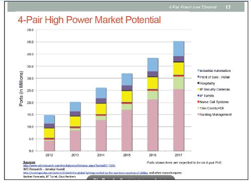
The arrival of new PoE-powered devices, which require more power than the current 802.3at standard (25.5W), has led to the development of a new PoE standard capable of supporting higher power levels. The initial goal of this new standard is to utilize all four pairs of the cable (previously only two pairs were used) and thus achieve power levels of around 50W. Some of the devices requiring higher power include computers or virtual machines (Thin Clients), high-resolution IP cameras, next-generation access points, network-attached storage (NAS) devices, and even LED lights, which are also beginning to be powered through the existing twisted-pair cabling. It is estimated that this market could reach a business volume exceeding $400 million by 2020. It is worth noting that high demand is expected for this application to power equipment used 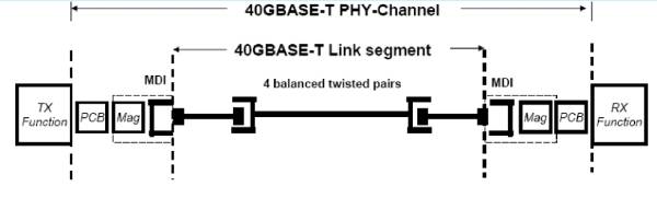 in building management systems (BMS), as shown in the following figure.
The development of this application assumes that all cabling systems can be used as long as the DC loop resistance does not exceed 25 Ohms. All CommScope cabling systems (SYSTIMAS and UNIPRISE) from Category 5E upwards will be compatible with this new PoE standard.
ANSI/TIA 568-C.2.1 - Twisted Pair Cabling for 40Gbps.
In the current version of this draft, there are already some important points that we will discuss. The maximum distance and connection model for the new Category 8 systems are defined: 30 meters and a maximum of 2 connections, with a bandwidth of 2GHz. Current work is based on modeling the components and harmonizing the solutions with respect to the characteristics of the components developed within 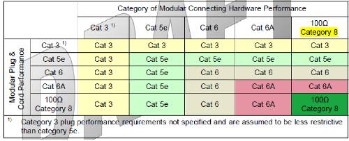 ISO/IEC TR 11801-99-1. It is important to highlight that the American standard for Category 8 only recognizes the RJ45 connector as the sole interface. The following table shows the mechanical backward compatibility of Category 8 components with those of previous categories.
Work is also underway on what has been termed an "End-to-End Channel," which is a patch cable with special characteristics, distinct from those used in standard cabling. Its purpose is to enable direct connections between devices, such as a switch to a server. Regarding cable size, the possibility of limiting the maximum diameter to 9 mm is being explored, although this point is still under review.
ANSI/TIA 568-0.D. Telecommunications Cabling for Enterprise Environments. Generic Aspects.
Work has begun on developing the general aspects that telecommunications cabling must meet when implemented in generic enterprise environments. Although it is still in a very early stage, there are several points we can comment on in the current draft. The nomenclature for defining the different distribution points that make up a structured cabling system, traditionally called MC (Main Cross-Connect), IC (Intermediate Cross-Connect), and HC (Horizontal Cross-Connect) according to this American standard, will be changed. From now on, and in a much more generic way 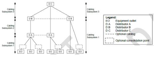 , they will be called DC, DB, and DA, respectively, which stand for Distribution Point C, B, and A. Similarly, the user outlets, which were usually called TO (Telecommunications Outlets), will be called EO (Equipment Outlets). All these nomenclature changes can be seen in the following figure.
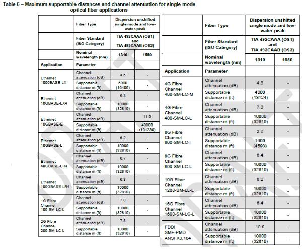
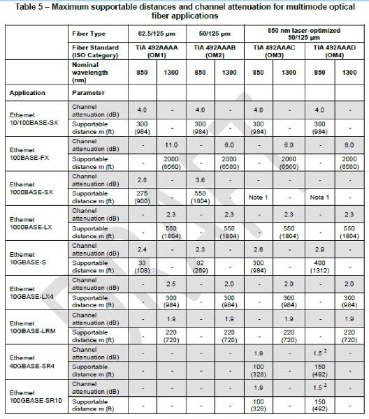
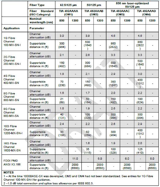
Another important point covered by this standard is the maximum permissible attenuation and distances for all Ethernet and Fibre Channel applications, using multimode and single-mode fiber as the transmission medium. These are listed below.
'
'
'
'
ANSI/TIA 942-A. Data Centers.
Work is underway on the final resolutions of the comments submitted by the various organizations that make up the working group reviewing this standard. In addition to the adoption of new topologies announced in the previous version of this document (fat-tree, full-mesh, interconnected mesh, centralized switch, and virtual switch), the most significant and recent change is that the maximum patch cord length that can be used in a data center for direct connections between equipment has been reduced from 15 meters to the current 10 meters.
Increasingly, the goal for data center cabling is to implement structured cabling and avoid direct connections between equipment as much as possible, both because of their lack of flexibility and because of the inferior technical performance compared to structured cabling that direct connections entail.
ANSI/TIA 4966 – Structured Cabling for Educational Environments.
The TIA 4966 standard, which outlines the technical characteristics, performance, and recommendations for implementing structured cabling in educational environments such as universities, schools, etc., has finally been approved for immediate publication. This standard follows the principles of the generic EIA/TIA 568C standards regarding cabling topology and maximum distances, and EIA/TIA 569C regarding conduits and technical spaces. It is worth noting that this standard recommends the use of Category 6A and OM4 fiber for new installations, as well as Category 3 multipair cables for voice trunks if conventional analog telephony is planned. Importantly, it also includes recommendations for sizing the cabling to support access point connections for Wi-Fi coverage. The recommendations are as follows: - In entrance halls or reception areas, 1 access point per 150 m² - In areas where 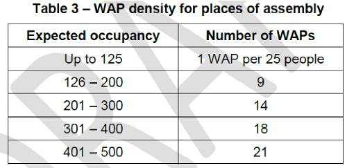 students, teachers, and administrative staff will be concentrated, such as classrooms, conference rooms, gyms, cafeterias, etc., the number of access points required will depend on the expected number of users. The following table shows the number of access points based on the number of users.
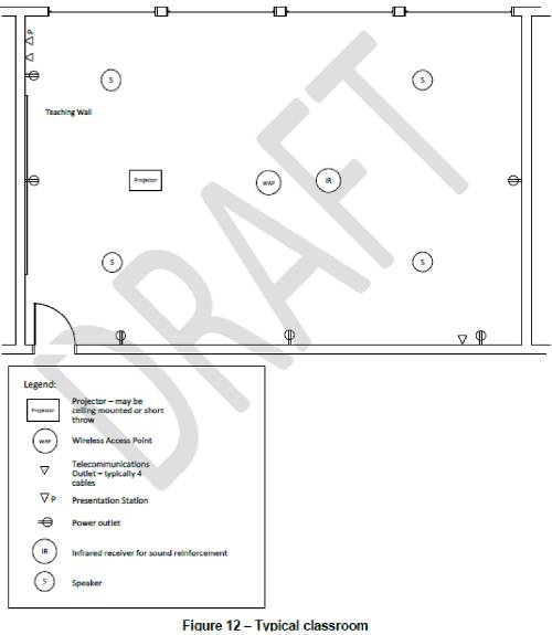
It is also recommended that access points be located at a height between 2.4m and 3.6m above the floor, and never exceeding 9m in height, considering that as the installation height increases, the coverage area of the access point decreases. The following figure shows an example of typical installations in a classroom.
For informational purposes, this standard also includes recommendations for implementing a Distributed Antenna System (DAS) in these environments.
The reasons for installing a DAS in an educational setting, or indeed in any other environment, are listed below:
- To have a single distribution system for all telephone operators wishing to provide coverage at the facility.
- To avoid the need for repeated actions by different operators to improve coverage, maintain telephone infrastructure, etc., as this centralizes the entire process.
- To provide a telephone system that allows operators to have more transmission equipment, thus preventing network capacity issues.
- To ensure adequate coverage throughout the entire environment.
'
The following figure shows the typical distribution scheme of a DAS system.
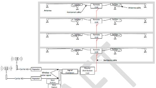
As you can see, there will be a "master" unit at the headend, fed by external antennas, and remote units that will in turn be fed, typically via coaxial cable or single-mode fiber optic cable, from the master unit. Coaxial cables will run from the remote units to feed the various passive antennas common to all operators in the installation.
ANSI/TIA TSB 162-A – Wi-Fi Cabling:
The latest version of TSB 162-A, which outlines the technical specifications and implementation recommendations for structured cabling to support Wi-Fi networks, is now finalized and ready for publication. This document serves as a guide for implementing Wi-Fi systems in environments such as commercial buildings, educational institutions, hospitals, restaurants, hotels, and outdoor areas. It is important to note that electromagnetic waves are significantly affected by commonly used building materials. Therefore, depending on these materials, propagation and attenuation conditions can change, and consequently, the expected coverage levels may not always be achieved. In general, the design guidelines in this document focus on achieving minimum signal levels in the desired areas, without considering building materials, the number of users, or network capacity. For a complete and detailed coverage study, taking into account construction materials and minimum capacity or speed per user, a thorough coverage analysis is necessary using modeling software tools that consider all these parameters. The deployment of user outlets, typically located 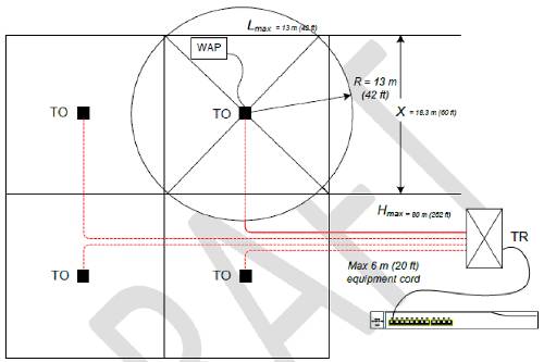 in suspended ceilings where Wireless Access Points (APs) will later be connected, is based on creating grids to maximize the coverage area of each AP. These grids or cells are shown in the following figure.
As can be seen, the maximum cell side length will be 18.3 m, which means the maximum AP coverage radius will be 13 m.
This document recommends placing at least two RJ45 jacks or connectors in each cell, or ultimately in each outlet (TO), to allow for two access points in the same location, or even to connect APs that have more than one RJ45 connector.
It is also recommended that the copper cabling used be Cat6A or higher, and if using fiber optic cable, it should be OM3 or higher.
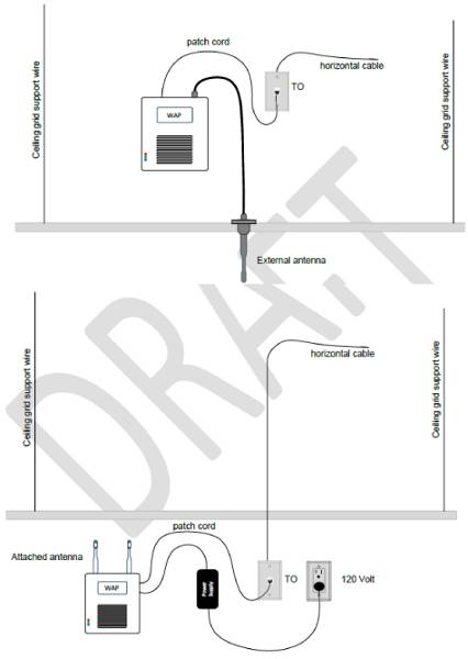
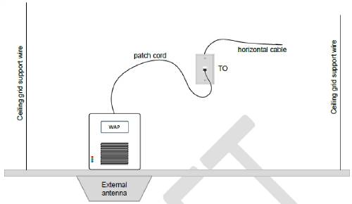
The following figures show examples of Access Point mounting.
Author: Alberto Martínez Technical Manager, Spain&Portugal CommScope Enterprise