PROTObus MAG, the serial data debugging toolkit.
PROTObus MAG delves deeper into serial bus standards than any other analyzer on the market. It includes five timing parameters, three bus utilization measures, and two tools for extracting digitally encoded data from a message and graphing it as if it were an analog signal. These are essential capabilities for engineers who need greater detail in analyzing the protocol in question and how it interacts with other circuit elements in an embedded design. The most powerful feature of PROTObus MAG is its ability to extract digital data from the
serial data message using the "Message to Value" parameter. Then, by applying a mathematical operator, "View Serial Encoded Data as Analog Waveform," the user can see a graph of these data values versus time—a capability not available in any other product. Examples of the usefulness of this capability include: viewing temperature sensor data sent over an I2C or SPI bus; IQ modulated radio frequency information sent over DigRF 3G; or the rotational speed of a wheel used by an ABS system and sent via CAN. The ability to convert the digital data embedded in the serial data message to an analog value and view an analog waveform representation of the data is a powerful feature that makes PROTObus MAG a must-have for serial protocol debugging engineers.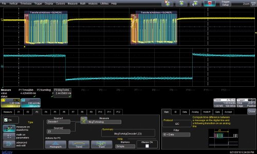 PROTObus MAG also includes automatic time measurements that are very useful for embedded designs for cause-and-effect validation, such as Message to Analog, Analog to Message, or Message to Message. These measurements provide the ability to quickly and accurately validate the operation of embedded systems, as well as perform statistical analysis of the measurements using Lecroy's powerful processing tools, such as histograms. For example, a serial data message sent by an embedded controller could result in another signal or message in the same or a different embedded controller.
By automating the timing measurements between these two events, and enabling rapid collection and analysis of large amounts of data, the validation of embedded systems can be faster and more accurate, and the presence and cause of timing violations can be easily located. Other included measurements, such as Bus Load, Message Bit Rate, and Number of Messages, provide an
overall picture of the serial data message traffic, allowing for a quick assessment of whether the bus is being saturated and whether the speed meets expectations.
ARINC 429 Symbolic Decoding:
ARINC 429 is a technical standard used primarily in avionics data buses implemented in high-end commercial and transport aircraft. It defines the physical and electrical interfaces of a two-wire data bus and a protocol to support aircraft avionics. Initially, testing tools for the ARINC 429 (Aeronautical Radio, Incorporated) bus consisted of bus analyzers, which, while very powerful for simulating and capturing large amounts of data, lacked the ability to view the physical layer waveform and required much longer setup times than an oscilloscope. Now, in less than a minute, the user can have the oscilloscope ready to view ARINC 429 traffic and to search for and capture areas of interest. Furthermore, the ARINC 429 solution offers a symbolic decoding function that allows loading a user-defined file to be applied to the decoded values and convert them into a more useful format. For example, the ARINC 429 bus of a Boeing 767 transfers data from an airspeed monitor, reporting the data in hexadecimal format. With the symbolic decoder, the resulting decoded message will be AirSpeed = 45 knots.
The ARINC 429 symbolic decoder uses the popular Lecroy interface, supported by color coding overlaid on the waveform, allowing for easy and visual discrimination between words and subwords.
The ability to view data in tabular format transforms the oscilloscope into a protocol analyzer. The table lists the ARINC 429 words in a tabular format and assigns a time code to each,
as well as a label, SDI, DATA, SSM, parity, and symbolic information. The MIL-STD-1553 decoding and triggering option complements the ARINC 429 decoder, providing a much-needed debugging toolkit for the commercial and military aviation industries.
USB 1.x/2.0 Decoding:
USB (Universal Serial Bus) 2.0 is a specification for establishing communication between devices and a controller (host). LeCroy has leveraged its expertise in USB 2.0 protocols, specifically its Voyager protocol analyzer, by integrating it into oscilloscopes. While USB 2.0 is widely considered the benchmark standard for embedded systems, it still presents some
challenges as it is used in newer applications such as smartphones, PDAs, and video game consoles.
The need for USB 2.0 debugging and analysis is currently addressed by protocol analyzers for protocol debugging and oscilloscopes for physical layer and compliance testing. LeCroy's USB 2.0 decoder integrates both capabilities into a single tool, significantly simplifying the debugging process.
The on-screen data table display offers the full power of a protocol analyzer, identifying the timestamp, device address, and endpoint. The powerful search engine, derived from the USB protocol analysis tools, allows for 45 search options, categorized by events, packets, transactions, and errors.
The USB 2.0 decoder also decodes low-speed (USB 1.0) and full-speed (USB 1.1) USB 2.0.
The MIPI (Mobile Industry Processor Interface) standard is driving the next generation of mobile devices—enabling faster data transfers, lower power consumption, high-resolution displays, and cameras. LeCroy addresses these needs with the launch of the most comprehensive testing solution for the mobile phone industry. The testing solutions are specifically designed to meet MIPI standards and include a package for automated physical layer compliance testing, as well as decoders for protocol-level troubleshooting.
For compliance testing, the QualiPHY MIPI-DPHY (QPHY-MIPI-DPHY) solution provides automated control of LeCroy oscilloscopes. For the debugging phase, the D-PHY decoder complements the QPHY-MIPI-DPHY package and decodes the physical (D-PHY), camera (CSI-2), and display (DSI) layers using color-coded overlays on various sections of the waveform across up to four data lines. Furthermore, the DigRF 3G interface decoder allows the user to quickly analyze the digital RF waveform, understand the protocol and information within each packet, and characterize it in time and amplitude while preserving the oscilloscope's exceptional response.
Data acquisition via Ethernet WiFi
Instrumentos de Medida, SL presents the new MSX-WL series of intelligent Wi-Fi Ethernet systems from Addi-Data, enabling precise and reliable signal data acquisition directly in the field. The systems can be easily configured from a work site on the network...