
 This article provides a detailed comparison between Ethernet and RapidIO technologies. RapidIO, similar to Ethernet, exchanges packets over different media.
RapidIO Technology Overview
RapidIO, similar to Ethernet, exchanges packets across different media. RapidIO supports email and read/write semantics, allowing control-plane and data-plane operations to use the same physical interconnect, a feature that improves efficiency and simplifies system design. Designed from the ground up to minimize latency, RapidIO technology has been optimized for hardware implementation.
RapidIO links guarantee packet delivery, even in the face of congestion and transmission errors, through simple flow control and error recovery mechanisms. These mechanisms are implemented using small, link-specific amounts of data called "control symbols." Most control symbols can be embedded within packets, minimizing control loop latency for reliable packet exchange.
Ethernet Technology Overview
Ethernet has always been an "imperfect" medium because it requires software support for protocols, such as TCP (Transmission Control Protocol), to provide reliable transport services. The flow control mechanisms typically used in Ethernet consist of network layer protocols, which control transmission rates based on packet loss detection, as this is the most effective way to ensure reasonable throughput across a global network.
Lately, there has been much talk about the concept of “lossless Ethernet,” also known as “Data Center Ethernet (DCE).” Lossless Ethernet reduces the number of packets lost due to network congestion by implementing flow control at the link level. This increases the overall efficiency of the network because it greatly reduces the number of lost packets. The performance of lossless Ethernet under congestion is comparable to that of RapidIO.
For a detailed comparison between RapidIO and Ethernet technologies, visit www.rapidio.org and read System Interconnect Fabrics.
Ethernet Versus RapidIO Technology.
No loss?
RapidIO guarantees packet delivery on every link. In the case of a 100m/10Gbps fiber optic connection, recovery can be achieved by exchanging three control symbols, a process that takes approximately 2.5 microseconds. In the case of a chip-to-chip link, the exchange takes place in less than 300 ns.
 The term "lossless Ethernet" is not entirely accurate, because the possibility of packet loss due to transmission errors still exists. Therefore, DCE, now as before, requires offload engines and/or software stacks, which increases message delivery latency. For example, the Fibre Channel protocol allows for error recovery in FCoE. Consequently, error resolution has much higher latency in Ethernet than in RapidIO, and this high latency has a considerable impact on resource utilization and system performance.
Dedicated Ethernet working groups are working to incorporate forward error correction (FEC) into the transmission scheme for higher data rates. While this can significantly decrease the likelihood of errors, it also contributes to higher latency for each transfer from one device to another across the network.
Two Ethernet Markets
Indeed, the Ethernet community is taking a completely new direction and dividing the market into two segments: Internet and DCE. In the context of the global Internet, flow control at the network layer provides higher throughput than flow control at the link layer. Due to Ethernet latencies on the global Internet and the dynamic network topology, network-layer flow control proves to be the most effective flow control strategy. Ethernet technology consists, for the most part, of Ethernet for the Internet.
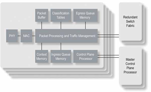
Ethernet technology for the Internet relies on processing power in the form of switch and router platforms. Within these platforms, network processing units (NPUs) regulate traffic according to established service-level agreements (SLAs) and implement network protocols such as MPLS. Figure 1 shows a typical Ethernet switch/router for the Internet.
 Lossless Packet Transfer:
Note that an Internet router or switch platform has a number of short-range connections between chips. The low latency of these short-range connections can be leveraged to minimize packet loss through simple flow control mechanisms. It should be noted that leading Internet Ethernet switch and router manufacturers do not use Ethernet as the sole interconnect technology in their own platforms. Instead, interconnect standards such as SPI (Serial Peripheral Interconnect), Interlaken, and RapidIO incorporate low-latency flow control mechanisms to ensure efficient, lossless packet transfer.
Unlike lower-latency DCE switches, Internet Ethernet switching chips can support the functions included in switch and router platforms. Therefore, some devices connected directly to DCE switches are responsible for these functions. This represents a significant shift from the simple transmit-receive architectures that characterize Internet Ethernet technology for most users.
The arrival of lossless Ethernet means the Ethernet market will be split into Internet Ethernet devices and DCE devices. DCE devices, however, cannot benefit from the same economies of scale as Internet Ethernet devices.
Throughput, Latency, and Flow Control:
In a data center network, latency for control functions, such as file modifications and data transmission acknowledgments, can significantly limit system capacity. Similarly, the latency of the control system for server load balancing functions can determine the overall system's usability and efficiency.
In this context, flow control mechanisms should allow control packets to advance their transmission as quickly as possible. In the event of contention, scheduling options should be maximized, fully utilizing buffers to increase throughput and reduce latency. Ideally, buffers should be managed so that high-priority flows can always be prioritized. The following section compares the flow control strategies of RapidIO and DCE.
A comprehensive flow control strategy
RapidIO implements a comprehensive flow control strategy to address system congestion in the short, medium, and long term. RapidIO's flow control mechanisms allow a transmitter to utilize the receiver's buffer capacity until it is exhausted. This is important for several reasons:
The more packets a switching chip stores in its buffers, the more opportunities it has to increase throughput by routing packets to uncongested output ports, which should result in maximum throughput and minimum latency.
The transmitter and receiver have agreed on how many packets can be transferred over each priority/virtual channel. The transmitter can use this information when scheduling packet transmission to optimize network latency performance.
The low-latency control mechanism minimizes RapidIO's buffer size while ensuring packet delivery and achieving line-level transmission rates.
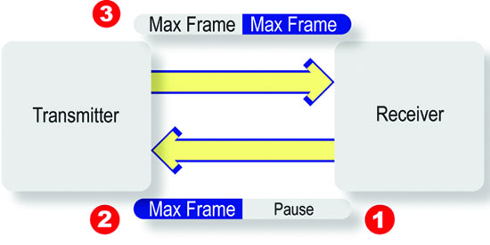
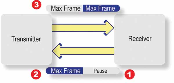
The flow control, based on the IEEE 802.1p priority standard, uses an XON/XOFF mechanism, which must be activated before the receiver's buffer space can be exhausted. Figure 2 clearly illustrates why the ability to include link-level flow control information in packets is such a significant advantage for RapidIO. At point 1, the receiver decides to disable a specific priority frame. However, the yellow MAX frame (point 2) has already started transmitting and prevents the transmission of the PAUSE XOFF frame. Thus, the receiver can receive the corresponding yellow MAX frame. Once the transmitter has received the PAUSE XOFF frame, a similar problem can arise at point 3, where a MAX frame has already started transmitting. Therefore, the minimum amount of information received after the XOFF transmission, i.e., the skid, that Ethernet links must take into account is two packets of maximum size.
For a 10 Gbps link with a length of 100 m, the estimated skid length is approximately 10.1 KB (http://www.ieee802.org/1/files/public/docs2008/bb-pelissier-pfc-proposal-0508.pdf). This calculation assumes a maximum packet length of 2,000 bytes. If other storage-related protocols are used, such as FCoE with a maximum transfer unit (MTU) of 2.5 KB or iSCSI with an MTU of 9 KB, the skid length will increase. And in other Ethernet initiatives, such as PEE (Power Efficient Ethernet), the skid length can be even greater.
 Relevance of skid length
For network interface cards (NICs) and processors with gigabytes of DRAM, skid length is irrelevant. However, for the small onboard memories found in switching chips, skid length is a concern. A large skid length has significant consequences for Ethernet switch designers and Ethernet data center users:
To prevent sending an XON followed immediately by an XOFF, more than the buffer skid length is needed before a flow is activated. This means that packets will be transmitted in certain flows, creating bursty traffic, which results in erratic network behavior.
There is no guarantee that the skid packets sent will meet the priority, which is then disabled. Therefore, a portion of the buffer reserved for skid will not contain packets, increasing latency and decreasing throughput.
To reduce the memory space required for an Ethernet port, one way to optimize the design is to group multiple priorities to control the flow. This can lead to head-of-line (HoL) blocking, with corresponding throughput drops and latency increases for all traffic in this priority group.
Flow control may also disable scheduling algorithms for packet transmission.
Short-term flow control has never been Ethernet's strong suit, but long-term flow control is. Typically, software-based flow control protocols rely on packet loss detection when Internet Ethernet devices drop packets in case of congestion. Since DCE no longer drops packets in case of congestion, long-term flow control is supported using the 802.1Q virtual LAN standard.
The RapidIO Gen2 specifications have created XON/XOFF as well as rate- and credit-based flow control mechanisms for packet-based data streaming. This mechanism is designed for systems with multiple senders and a single destination. The protocol allows senders to communicate the amount of data available, and the receiver to manage and schedule which senders are active and at what speed. Unlike software-based flow control mechanisms, the packet format is so simple that the hardware can support these mechanisms. If used correctly, these flow control mechanisms can prevent long-term congestion and enable applications to perform optimally.
Overcoming Congestion:
One method for resolving network congestion and flow control issues involves communicating where traffic is bottlenecked in the network. This information allows packet transmission to be scheduled at the source to travel through uncongested areas of the network. RapidIO supports mechanisms for communicating congestion locations. RapidIO Gen2 defines a low-latency mechanism based on control symbols called Virtual Output Queue (VoQ) Backpressure. Virtual Output Queue (VoQ) Backpressure defines a hierarchical, hardware-implementable method that pushes congestion to the network margins. This method offers two advantages:
It slows down flows that contribute to congestion points, freeing up system resources.
It prioritizes the transmission of other flows that do not increase congestion, thereby increasing throughput and balancing the system load.
In 2010, an IEEE working group began defining a similar mechanism, known as IEEE 801.3Qau – Congestion Notification for Local and Metropolitan Area Networks. It is unclear whether this mechanism will be simple enough for devices within the DCE ecosystem to support.
Conclusion:
While researching the topic of this article, I came across another by Stuart Cheshire, first published in 1996, with the provocative title “It’s the Latency, Stupid” (http://www.stuartcheshire.org/rants/Latency.html
). Although his article focuses on latency in consumer Ethernet for the Internet, its essential points still seem valid today:
• Increasing bandwidth is easy.
• Expanding limited bandwidth is easy.
• Once bad latency is established, it is difficult to eliminate.
Mass-market Ethernet, i.e., Ethernet for the Internet, focuses on delivering more bandwidth for less money.
Data Center Ethernet has features that will increase throughput and improve the performance of Ethernet for the Internet in the data center. However, these features negatively impact Ethernet chip design, and they still require software and/or offload engines for recovery after a transmission error. The Data Center Ethernet market is much smaller than the Internet Ethernet market; therefore, the economies of scale that result in inexpensive Internet Ethernet technology are not applicable to Data Center Ethernet.
Applications that have adopted RapidIO require low and predictable latency for chip-to-chip, board-to-board, backplane, and case-to-case communication. Leading companies in these systems (such as Ericsson, EMC, and Mercury) ensure that RapidIO will maintain low latency combined with high throughput to guarantee that the performance specifications of these systems are met. RapidIO will maintain bandwidth parity with other interconnects while preserving the fabric with the lowest latency and highest efficiency available for chip-to-chip, board-to-board, backplane, and fiber/cable connections up to 100 m.
About the author:
Barry Wood is an experienced applications engineer at IDT Canada. Barry joined IDT in 2001 after working for 11 years at Nortel Networks. Barry has extensive experience in fault-tolerant system design, software development, and hardware/software integration. Barry currently leads the RapidIO technical working group.
Author: Barry Wood, Applications Engineer, IDT Technologies

