
 Being aware of common mistakes in field checks can prevent project delays and excessive expenses.
Many difficulties can arise when performing tests, but many people are surprised to learn that the wiring identification scheme can cause some of the most serious headaches. When a test is complete, the result is saved in the tester. The filename used should match the wiring identification of the link. If this is done incorrectly, the user may refuse to pay. If you are lucky, an edit-and-replace sequence can be performed using the wiring identification from the software. Almost all field testers have the capability to preload the wiring identification scheme into the tester (provided the project owner has entered it correctly) to prevent this from happening.
Calibration
Did you specify that the field tester must have a valid calibration? The term calibration is often confused with establishing a field reference to eliminate the effect of the test leads. We should probably refer to this as “calibration with traceability.” The instrument must be calibrated according to traceability standards every 12 months or as specified by the test equipment suppliers according to IEC 14763-2 (draft). This standard states that test results must be accompanied by a valid calibration certificate.
Permanent link or channel test?
There are two definitions of links in testing standards. Permanent link excludes patch cords, over which the installer typically has no control. Channel is for the end user who wants to know the performance of the entire link, including the patch cords. Channel testing provides an opportunity to conceal a faulty installation. Not only are the test limits lower in channel testing compared to permanent link testing, but using a 5-meter cable at each end moves the connector further from the testing instrument, resulting in a more favorable outcome. The test report must detail the type of adapter used in the test along with the test limit. If the link is a patch panel to an RJ45 connector, the combination of a permanent link adapter at one end and a channel adapter at the other will be unacceptable. If you discover a channel adapter at both ends of the link and the test limit indicates a permanent link, you should seek further information.
 Marginal Results:
Contractual disputes over marginal pass results continue to arise. If the margin of the test result falls within the accuracy of the field tester, the result must be marked with an asterisk (*). This is defined in IEC 61935-1. The standard states that although the individual result must be marked with an asterisk, the overall result is still PASS, provided there are no failed parameters in the set of tests. Why does the dispute occur? The wiring system is often sold as a system of much higher quality than the standards. Thus, any marginal result can suggest a problem. Unless you specifically state that marginal pass results are unacceptable, you must accept the results. There is a user guide in IEC 14763-2 (draft) which states the following: “To minimize marginal test results, the quality plan should specify the properties of the field tester used in the test, in addition to taking into account the improved accuracy specifications in the measurements available through the field tester manufacturers.”
Test cables
The electrical performance of the permanent link test cable will be a concern and should not be taken for granted. It is well known that the NEXT associated with 8-pin RJ45 connection hardware is highly dependent on the connector's properties. IEC 61935-1 specifies that: “the connectors of the link adapters on field testers must fall within the range of test connectors defined as acceptable 8-pin modular connection hardware.” This range is deliberately narrow to ensure consistent results across all field testers. The electrical performance of the RJ45 connector at the end of the permanent link test cable is the greatest source of variability among test equipment vendors. While the test cable MUST use a NEXT-compliant RJ45 connector, there is no requirement for return loss. It is the user's responsibility to specify whether the RJ45 connector used for testing meets the NEXT and return loss requirements defined for Category 5e, 6, and 6A.
 Alien Crosstalk testing, as defined
by ANSI/TIA-568-C.2 and ISO/IEC 11801:2010, is still considered optional for Category 6A/Class EA cabling systems. However, IEC 14763-2 (draft) specifies four levels of acceptance testing, with Level 3 including Alien Crosstalk. Again, the end user is responsible for specifying whether or not to perform this test. Furthermore, a sampling plan for Alien Crosstalk testing, based on existing sampling standards, is now available for the first time. At a recent IEC meeting in Seattle, Washington, it was agreed to use an equivalent Acceptance Quality Level (AQL) of 0.4%, normal inspection, Level I general inspection as defined in ISO 2859-1, for populations of up to 500,000 links.
Level 1 and 2 Fiber Verification:
It is generally accepted that the optical loss of all fiber installations should be verified. IEC 14763-3 addresses Level 1 verification. Level 2 verification, which includes the use of an optical time-domain reflectometer (OTDR), is optional. According to ISO/IEC 11801:2010, we consider return loss an acceptance verification requirement for fiber optic cabling systems. The requirements are 20 dB for multimode connections and 35 dB for single-mode connections. These measurements are typically performed with an OTDR, suggesting that Level 2 verification is now necessary. If you think 20 dB is too low, you are correct. It has been left to allow for field polishing of multimode connectors. Reduced reflectance can lead to negative loss readings and cause attenuation dead zones to exceed the length of the link you are trying to measure. If you are specifying an OTDR check, avoid polished field connectors.
 Fiber Testing Methods
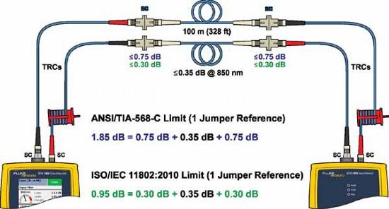
. Users are often confused when selecting between the North American standard ANSI/TIA-568-C and the international standard ISO/IEC 11801:2010. There are differences in the testing limits, and when it comes to fiber testing, there is a significant difference. ISO/IEC 11801:2010 refers users to IEC 14763-3 for fiber testing, where the first and last connections of a tested link must be greater than 0.3 dB for multimode and 0.5 dB for single-mode (Figure 3). In ANSI/TIA-568-C, the requirement is 0.75 dB. Why this difference? It is due to the way the fiber patch cords used in the testing are defined. The "test patch cords" must be greater than 0.1 dB for multimode and 0.2 dB for single-mode. At ANSI/TIA, there are currently no additional requirements other than the standard 0.75 dB loss.
Summary:
In an unregulated sector, the responsibility for understanding the specific requirements of each standard falls on the user and the installer. A number of standards exist on the market, and all users should have access to the internet and be able to find them. If you have any questions about their content, you can contact the cabling supplier who provides the cabling system warranty or the supplier of testing equipment. A little preparation beforehand can prevent financial penalties and delays in building occupancy.

