
 It is also necessary to splice the fibers that make up the cables at their ends, since in order to connect these fibers to the transmitting and receiving equipment that will use them, the installation of optical connectors is required, which are mostly made using patch cords (pigtails) which are more flexible fiber optic cables and terminated at one end with a connector whose tip has a high quality polish, which is done by automated processes in the factory or also connectors with a little more than a centimeter of fiber, polished in the factory and which can be connected to the fibers that make up the cable by means of splices.
 In an electrical conductor splice, the joint is made laterally; in optical fibers, the joint is made at the ends, since the guided light must exit one fiber and enter the next.
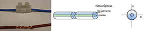
The optical fiber splice is performed by aligning the two fibers to be spliced so that their cores coincide along the horizontal and vertical axes (X, Y), as shown in Figure 1.
'
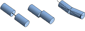
 Fiber alignment is the factor that most influences optical signal loss in fiber optic splices. It can be of three types: longitudinal (separation), lateral, and angular (Figure 2).
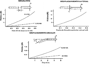
Optical signal loss will depend on the magnitude of the errors in these alignments and the characteristics of the fibers being spliced, including core diameters and other factors.
![]()
![]()
Numerical Apertures (NA) of the fibers (Figure 3).
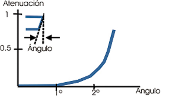
A very important factor in performing optical fiber splices, to obtain low losses, is the cutting angle with respect to the perpendicular to the axis: this must be less than 1° across the entire cut surface (Figure 4). Precision cleavers are used to make these cuts.
 Types of splices
If, after aligning the fibers, a fusion splice is made by applying a high-voltage electric arc or any other heating system, a fusion splice has been made; if the material is not melted, a mechanical splice has been made. (Figure 5).
'
Which type of splice is best?
Fusion splices are mainly used with single-mode fiber, and based on technical quality reasoning, we can assure that fusion splices are the best since they offer lower insertion losses and high return losses (fewer reflections). However, there are other reasons to consider when deciding which type to use, such as economic, technological, and logistical factors.
 Regarding economic reasons, it should be noted that mechanical splices require a lower initial investment (1200 to 1500 euros, depending on the quality of the tools) than that required for fusion splices (6500 to 10000 euros, depending on the quality and precision of the machine and tools), but the cost of consumable material for making each mechanical splice (²5 euros) is higher than for fusion splices, since once made it is only necessary to use a heat shrink protector with metal reinforcement whose cost is low (²0.25 euros/unit).
 The technological reasons will depend on the type of industry in which the splices are performed. In the telecommunications and CATV network sector, single-mode fibers are used, and where cable lengths are long, splices with low insertion loss are required, making fusion splicing the most suitable. However, for short-distance links (FTTx), both methods can be used. The security sector typically uses multimode fibers and short distances, so both types of splicing can also be used. LAN networks generally use single-mode and multimode fibers over short distances; therefore, either solution is suitable. For the industrial control sector (aerospace, automotive, building control, sensors in hazardous areas, etc.), the fibers are multimode and the distances are very short; therefore, mechanical splicing is also appropriate.
Regarding logistical constraints, it should be noted that the space required for mechanical splicing is less than that needed for fusion splicing, and that while the latter requires energy (although in recent years it has come from batteries), mechanical splicing does not require any type of power supply.
![]() These characteristics make mechanical splices very suitable for carrying out quick repairs, although in some cases these may be temporary.
These characteristics make mechanical splices very suitable for carrying out quick repairs, although in some cases these may be temporary.
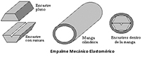
Mechanical splicing
involves joining the two ends of the fibers in a mechanical support to allow alignment of the coatings, using adhesives or pressure systems to prevent fiber separation. The interior is impregnated with index-equalizing gel to reduce insertion and return losses caused by light reflections resulting from differences in the refractive indices of the fiber core and air.
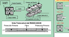
 The mechanical support has a groove that allows for the alignment of the fiber cladding and is usually V-shaped, which provides high alignment accuracy. See Figures 6 and 7.
For a mechanical splice to be used, the fibers to be joined must have very low eccentricity levels, or in other words, the center of the core must coincide with the center of the cladding. Otherwise, the insertion losses would be very high, especially in single-mode fiber splices.
Mechanical splices have been frequently used in testing laboratories, indoor installations, and with multimode fibers due to the tedious, complex, and delicate nature of the assembly and the importance of the mechanical stability of the components. The expansion or contraction of the materials due to temperature changes made them unsuitable for outdoor use unless they were of high quality and high cost.
Technological advancements in recent years have enabled the development of easy-to-install, robust, reliable, compact, and affordable mechanical splices.
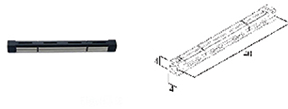
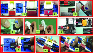
The Fujikura FMSEZ-025/09 mechanical splices (Figure 8) are an example of high-quality, compact splices (40 x 4 x 4 mm) that can be installed in splice box trays and allow for splicing single-mode and multimode fibers with 250 µm and 900 µm primary shielding.
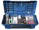
They can be assembled in less than 3 minutes with very few tools, which are transported in a small plastic case (Figure 9).
Once assembled, they independently secure the fiber coatings and primary shielding, preventing the fibers from rotating inside. This process is shown in Figure 10.
Features
The technical characteristics of the Fujikura FMSEZ-25/09 mechanical splices are indicated in Table 1.
Assembly
: To perform the splice, follow these steps:
1. Place the splice in the assembly tool.
2. Open the splice.
3. Place the fiber in the corresponding support with approximately 4 cm of fiber at the end.
4. Strip the fiber.
5. Clean.
6. Cut.
7. Place in the tool.
8. Repeat steps 3 through 7 for the other fiber.
9. Close the splice.
10. Release the fibers and remove the splice. (Figure 10).
tests
according to the Telcordia GR-765-CORE Generic Requirements for Single Fiber Single-Mode Optical Splices and Splicing Systems standard, demonstrating that these splices offer characteristics close to those of fusion splices.
The FMSEZ-025/09 is a splice that can be used with 250 µm and 900 µm primary shielding fibers; the tests were performed with fibers of these shielding thicknesses.
Fibers with 900 µm primary shielding withstand different environmental conditions depending on the plastic material of the shielding; therefore, the temperature tests were performed with fibers with PVC primary shielding (Table 2).
Tests were conducted in different categories corresponding to:
- Packaging, transport, and receiving.
- Installation and assembly.
- Environmental conditions.
Packaging, Transport, and Reception:
The splices were subjected to horizontal and inclined drops onto different types of surfaces.
Vibration tests were performed between 10 Hz and 500 Hz.
The splices were subjected to temperatures between
60 °C and -40 °C and relative humidities up to 90%.
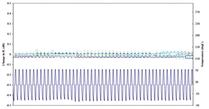
After each test, the splices were assembled, and the insertion and return losses were verified, confirming that the characteristics of the splices did not deteriorate, as average insertion losses of less than 0.15 dB and return losses greater than 40 dB were obtained in all cases (Figure 12).
 Installation and assembly conditions:
The splices were assembled at 0°C without humidity control; assemblies were also performed at 38°C and approximately 90% relative humidity, and finally, the splices were assembled at 45°C and 15% relative humidity.
The insertion and return losses of the splices were verified, and average insertion losses of less than 0.15 dB and return losses greater than 40 dB were obtained.
Environmental Conditions:
The splices were subjected to different environmental and mechanical conditions to verify whether insertion losses increased or decreased return losses.
The tests performed were as follows:
- Tension between the two fibers of 4.4 N for 1 second.
- 50 temperature cycles from -40 °C to 75 °C.
- 15 humidity and condensation cycles from -10 °C to 65 °C.
- Immersion in water at 43 °C for 7 days.
- Vibrations of 0.76 mm amplitude and frequencies from 10 to 55 Hz in 1-minute sweeps and a total of 2 hours for all three axes.
- The temperature and tension cycles were repeated.
The results are shown in Table 3 and Figure 13.
Author: Pedro Notario, Technical Director TELECOM-UNITRONICS


