
 However, debates are ongoing in regulatory forums and technical symposia regarding the advantages and disadvantages of these fibers. Do they add value to data centers or enterprise applications? Are they necessary? Have these fibers been thoroughly researched? Are BI-FMM fibers capable of supporting high-speed applications of 10, 40, and 100 Gb/s over the same link distances as OM3 and OM4 standard fibers? This article attempts to answer these questions.
What is different about bend-insensitive fibers?
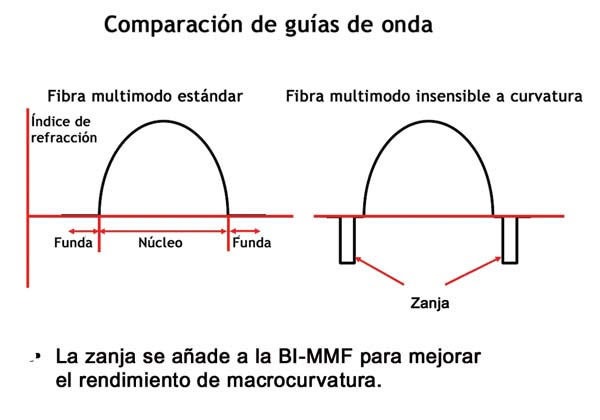
What makes a multimode fiber bend-insensitive? BI-MMF is not simply a multimode fiber standard with lower bend loss. It is a new fiber design that alters the light-guiding region, or “waveguide,” to improve bend loss (macrobending) performance. This is done by trenching around the fiber core, changing the properties of the guided light (see Figure 1).
Changing the waveguide of optical fiber is a complex process that affects many other fiber properties, which in turn must be optimized. In reality, changes made to improve bend loss often degrade other properties—including bandwidth and connection loss—which impacts system performance. The key question is: Does deploying bend-insensitive multimode fiber improve the performance of an installed multimode fiber link?
 FS and other manufacturers have examined the changes made to improve bend performance, and the results have both advantages and disadvantages. Studies have shown that bend insensitivity can come at a high cost, both in bandwidth and connection loss. To make matters worse, current standards requirements, especially those for laser-optimized bandwidth, do not account for the changes made to the waveguide of the BI-MMF fiber. This can lead to systems with worse performance than would be expected using current methods for estimating the fiber's laser bandwidth.
Tight bends and kinks in a 1.6 mm or 2.0 mm jumper can negatively impact the mechanical reliability of the link. Studies have shown that sharp bends in a jumper (such as those that might occur when a jumper is near a cabinet door) can lead to fiber breaks. Encouraging installation practices that result in tight bends and kinks by using BI-MMF fibers in a data center is mechanically hazardous and unnecessary. Modern cable management systems and common, easy-to-install practices allow for high density with reliability.
Today, BI-MMF fibers can reduce system performance in data center and enterprise applications. Therefore, high-performance, standardized OM3 and OM4 fibers are better choices for high-speed enterprise networks and data centers.
 A detailed analysis:
Since BI-MMF fibers have not yet been standardized by the industry, it can be difficult to define them precisely. However, a general definition of BI-MMF fiber would be helpful before discussing the advantages and disadvantages required in the manufacture of this fiber. It has been suggested that this new type of fiber should have the following macrocurvature attributes:
< 0.1 dB at 850 nm with 2 turns around a hose with a radius of
15 mm.
< 0.2 dB at 850 nm with 2 turns around a hose with a radius of 7.5 mm.
BI-MMF fiber was developed to simplify cable management. The goal of the new design was to reduce bend loss while maintaining all the specifications currently listed for OM2, OM3, and OM4 multimode fiber. However, existing fiber standards and system design principles were developed for multimode fiber with a traditional waveguide. BI-MMF, with its added trench, has a different waveguide. As a result, many current measurements and standards do not accurately describe or predict BI-MMF performance. It is important to note that, unlike single-mode fiber, improved macrobending performance in multimode fiber does not necessarily lead to improved microbending performance. Switching to BI-MMF will not improve the microbending performance required in some cabling designs.
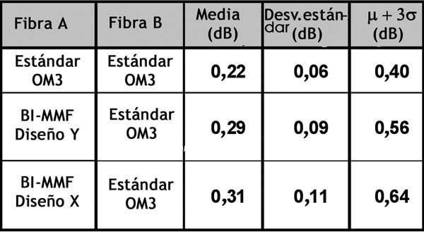
 Evolution of the Ethernet standard (and other data networking standards) has resulted in increased data rates and reduced channel insertion loss for short-haul links. Channel insertion loss encompasses many properties, including cable attenuation, connection loss, and macrobend loss. BI-FMM exhibits higher connection loss when connected to standard multimode fiber (see Table 1). Simply reducing macrobend loss offers little benefit if other contributors to link loss increase. If the goal is to minimize link loss, it is illogical to "trade in" a higher default connection loss (and link loss) to protect against potential sharp bending that can be prevented through proper cable management. Furthermore, such a trade-off could introduce a mechanical failure point with a tensioned twist point.
Changing the Way Light Travels:
Due to the trench, light is guided differently in BI-MMF than in standard fiber. This is necessary to decrease the amount of light lost in a macrobend. To understand this difference, it's important to know that modes propagating in multimode optical fibers can be classified as:
• Guided modes: modes with an efficiency index greater than the cladding index.
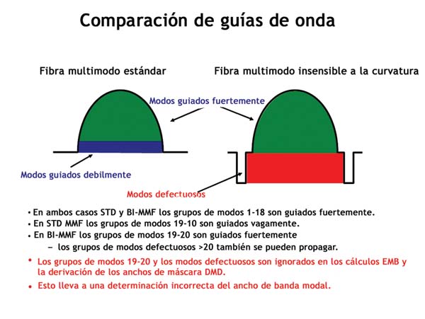
• Faulty modes: modes with an efficiency index less than the cladding index (these are often referred to as "cladding modes").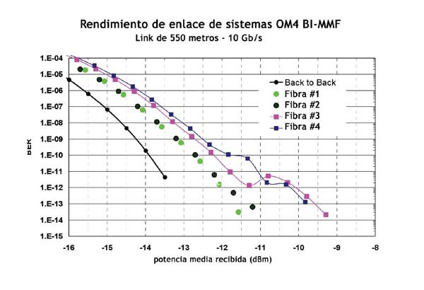 When light travels closer to the core/cladding interface, the modes are less tightly bound in the center and are more easily deflected by a macrobend in a standard fiber. These higher-order guided modes can be classified as weakly guided modes. By adding a trench around the core of the optical fiber guides, these higher-order modes are more effectively channeled, creating a multimode fiber with improved macrobending performance. The trench can also lead to an unfortunate side effect: defective modes, which do not propagate in a standard fiber, can propagate for several hundred meters in a BI-MMF fiber and must be accounted for in connection loss and bandwidth calculations (see Figure 2). The difficulty in measuring the connection loss of BI-MMF fiber is largely due to the challenge of accurately accounting for the two defective modes and the light that is now strongly bound to the higher-order modes.
Adding more tightly bound higher-order modes and leaky modes can have serious consequences for system performance. Neglecting these modes in a BI-MMF fiber can lead to overly optimistic system performance expectations. These modes may not have been considered in the development of laser-optimized fiber standards because the light was poorly guided. With the addition of the trench, these modes must be included in bandwidth calculations, and standards need to account for the difference in how BI-MMF fiber guides light. The practice of omitting these modes in a BI-MMF fiber, as suggested by some manufacturers, can lead to an incorrect determination of the modal bandwidth for laser-based systems.
Measuring Bandwidth in Bend-Insensitive Fiber:
Bandwidth requirements for high-speed, short-haul networks have evolved from the early days of light-emitting diodes (LEDs) to vertical cavity surface-emitting lasers (VCSELs).
With each successive increase in transmission speed, bandwidth requirements for multimode fiber have increased, and loss predictions have become more stringent. BI-MMF fiber can improve loss prediction in situations involving tight bends (depending on the added connection loss), but how does this affect bandwidth?
 The data-carrying capacity of a multimode fiber is a function of its modal bandwidth. The modal bandwidth specifications in the IEEE 10G, 40G, and 100G Ethernet standards were developed based on a sophisticated model predicting the launch behavior of a VCSEL with a standard multimode fiber waveguide. These requirements were then translated into the TIA specifications, which are used to ensure that OM3 fiber will have 2000 MHz/km and OM4 fiber will have 4700 MHz/km of modal bandwidth in deployed systems. However, the models used to develop the bandwidth specifications in the TIA are not valid for BI-MMF fibers, where light is guided differently within the fiber. Therefore, the bandwidth performance of these BI-MMF fibers is not defined in current high-speed networks. This is one of the major concerns with BI-MMF fibers.
When pulse dispersion measurement (DMD) and system bandwidth modeling were developed to determine multimode fiber bandwidth, it was assumed that only the first 18 mode groups would propagate in the fiber, and that the 18th mode group would be highly attenuated. Therefore, simulation models for EMB mask widths and DMD used only 17 mode groups. BI-FMM fibers propagate both guided and leaky mode groups, which are not accounted for in current laser-optimized bandwidth calculations, and these modes can significantly degrade bandwidth if ignored. The potential result: a modal bandwidth that is significantly lower than expected, leading to low link margins or even system failures.
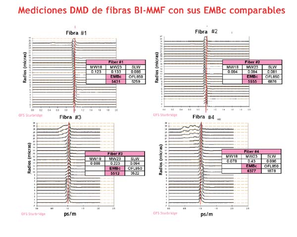
To illustrate this problem, the DMDs of the four commercially available fibers that clearly meet the 4700 MHz/km calculated effective modal bandwidth (EMBC) required for OM4 were examined (see Figure 3).
All fibers had comparable EMBC bandwidths, but fiber number 4 failed the DMD mask method for determining the bandwidth of the OM4 multimode fiber. Both fiber number 3 and fiber number 4 had poor higher-order mode control, indicating poor control of the fiber core deposition near the core/cladding interface.
When inserted into a 550m 10 Gb/s link, fibers 3 and 4 performed poorly, while fibers 1 and 2 performed as expected for OM4 fiber. Figure 4 shows that system penalties for fibers with poor higher-order mode control are significantly greater than for fibers with good all-mode control. This performance variation indicates that significant work is needed to properly classify bandwidth in BI-FMM fibers. Higher-order modes (17, 18, and higher-mode groups) propagating in BI-FMM fibers can significantly worsen system performance than anticipated by current standards.
The OFL bandwidth values illustrate the usefulness of this parameter in ensuring system performance, but the current requirement of 3500 MHz-km may not be sufficient for visualizing BI-FMM fibers due to their higher-order mode behavior. Fiber 4 has good EMBc but fails in OFL bandwidth, resulting in poor system performance. Fiber 3 has marginal OFL bandwidth and poor system performance, while the two fibers with high OFL values (> 5000 MHz/km) have very good system performance.
As more modes become more prevalent, achieving high bandwidths becomes more difficult. This led to the fiber market's transition from 62.5/125 µm fiber to 50/125 µm fiber; fewer modes to control have allowed for the development of higher-bandwidth fiber. This has enabled bandwidth to increase from the 160 MHz/km required for FDDI to over 2000 MHz/km at 850 nm (OM3), and to the 4700 MHz/km of OM4 fiber required by current Ethernet standards. With higher-order mode groups, more strongly guided modes, and additional leakage modes, BI-MMF may be a step in the wrong direction in our pursuit of 100 Gb/s Ethernet with 25 Gb/s lane and 32 Gb/s Fibre Channel.
 Mechanical Reliability:
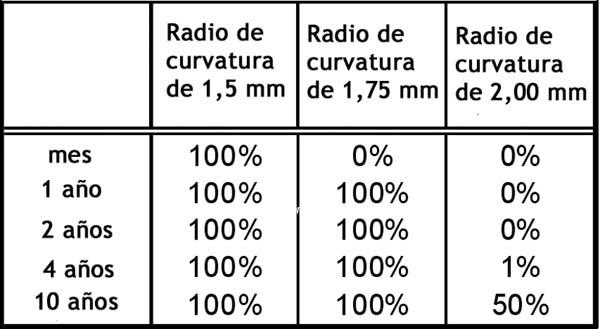
The mechanical reliability of an optical fiber jumper can be negatively affected by the bend radius. Link reliability depends not only on optical strength but also on the mechanical strength of the components. BI-FMM fibers have the same mechanical properties as standard fiber, and uncontrolled tight bends can cause mechanical failure. In other words, a twist point on a platform edge or a jumper caught in a cabinet door significantly increases the likelihood of mechanical failure (such bends can have a bend radius of 2 mm or less).
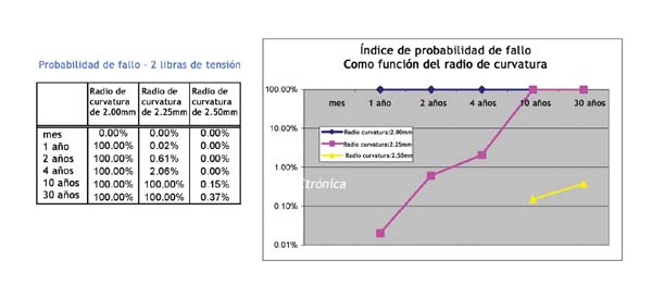
In bend-insensitive single-mode fibers, this was addressed by a significantly larger diameter of 4.8 mm, limiting the fiber's bend radius to approximately 5.0 mm. However, with a 2.0 mm cladding, the minimum bend radii can be considerably smaller. Studies demonstrate that bend radii of 2.0 mm or less have a high probability of failure. Any tension on the fiber creates additional stress and accelerates the failure rate far beyond that shown in Table 2. Adding just two pounds of tension increases the probability of failure to 100% within one year (Figure 5).
Increasing optical reliability provides no benefit to the end user if mechanical reliability is compromised by poor installation. In fact, it can be argued that it is beneficial for a standard fiber to exhibit high loss in systems with very tight bends, forcing the installer to correct these poor installations to help ensure system robustness throughout its expected lifespan. An unexpected link failure six months after installation and a system upgrade could have catastrophic consequences in today's high-performance data centers.
Conclusion:
There are many important questions surrounding bend-insensitive multimode fibers. Issues related to backward compatibility and bandwidth performance must be resolved before widespread implementation of this fiber. System reliability, including mechanical reliability, is critically important to enterprise customers. Standards groups such as TIA are an excellent forum for studying BI-MMF fibers and defining their performance. These industry groups can ensure that current and new standards accurately evaluate and verify the performance of next-generation multimode fibers. Meanwhile, the risk of uncertainty in BI-MMF performance outweighs the limited benefit it offers to enterprise cabling systems.
Author:
John Kamino, OFS Product Manager, and David Mazzarese, OFS Technical Marketing Director.


