
 Supporting Ethernet, FibreChannel, and OIF applications, OM4 fiber enables extended reach of up to 550 meters at 10 Gbps for extra-long building backbones and mid-distance campus backbones. It offers an effective modal bandwidth (EMB) of 4700 MHz-km, more than double the IEEE standard for 10 Gbps support over 300 meters.
To help you use this advanced fiber to its fullest advantage, this article describes the technology behind OM4 fiber, highlighting the main differences with other fiber types, and explaining how its high bandwidth is guaranteed through the most rigorous measurement methods.
Multimode Fiber Fundamentals
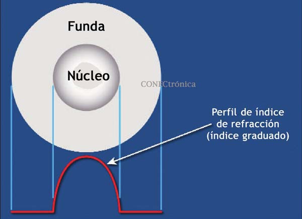
: Compared to single-mode fibers, multimode fibers have larger cores that, as the name suggests, guide multiple “modes,” or light rays, simultaneously. Modes traveling toward the outer edge of the core have a greater distance to traverse than modes traveling near the center.
The graded-index profile of the core is designed to minimize the distance traveled by modes with shorter paths, ensuring that all modes reach the fiber end as close together as possible in time. This reduces pulse dispersion, also known as DMD, and maximizes bandwidth, which is the amount of information that can travel through the fiber per unit of time.
In addition to their large core, multimode fibers have a large numerical aperture (NA), the maximum angle at which a fiber can accept transmitted light. This allows them to operate with relatively low-cost optical components and light sources such as light-emitting diodes (LEDs) and VCSELs.
Multimode Fiber Options.
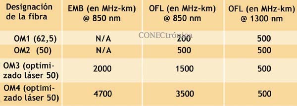
Multimode products are identified by the OM (“multimode optic”) designation as specified in the international cabling standard ISO/IEC 11801 (see Table 1).
OM4 fiber is the latest development in this series. It is particularly well-suited for short-haul data centers and high-performance computing applications where expected optical losses are 10 Gb/s (and are expected to be closer to 40 Gb/s and 100 Gb/s). The high bandwidth provided by OM4 fiber when deployed over shorter distances than its nominal length offers extra headroom for channel insertion loss.
 OM4 is compatible with applications requiring OFL bandwidth of at least 500 MHz-km at 1300 nm (e.g., FDDI, IEEE 100BASE-FX, 1000BASE-LX, 10GBASE-LX4, and 10GBASE-LRM).
The latest offerings in multimode fiber are 50-micron bend-insensitive multimode fibers (BIMMFs). These fibers have been touted as offering all the advantages of high-bandwidth laser-optimized multimode fiber, with the added benefit of lower bend sensitivity.
However, recent work has raised some concerns about these fibers. Studies have identified problems with the characterization of bend-insensitive fibers and have questioned whether current requirements are adequate to ensure system performance. Other studies have shown that connection loss between BIMMFs and standard fibers is higher than between standard fibers and other standard fibers. This additional loss adds to the total loss of the link.
It has been proposed that standards organizations conduct a thorough review of BIMMFs and incorporate it into industry standards. Until this is done, caution is advised before widespread adoption occurs.
What makes OM4 fiber different?
Like OM3 multimode fiber, OM4 fiber is considered "laser-optimized," or optimized for use with VCSEL light sources. OM3 and OM4 fibers are designed and manufactured to maximize the performance of VCSELs compared to LEDs. For this reason, laser-optimized fibers are specified using laser bandwidth, or EMB. OM2 fiber, while compatible with VCSELs, is not considered laser-optimized. OM2 fiber is designed for use with LED light sources at speeds of 10 or 100 Mbps, or in short-haul 1 Gbps networks. OM2 fiber can be used with VCSEL, but its performance is limited to 550 meters at 1 Gb/s, and only 82 meters at 10 Gb/s, compared to the OM4 fiber range of over 1000 meters at 1 Gb/s and 550 meters at 10 Gb/s.
As mentioned, the speed at which each mode travels through a multimode fiber core depends on its refractive index, which is governed by the amount of germanium chemical dopants at that location in the core. Because modes traveling toward the center of the core have less distance to travel than those traveling toward the edge, the refractive index profile of a multimode fiber must be “graded” in a parabolic shape across the core. This slows down the modes that have a shorter distance to travel, equalizing the arrival time of all modes.
The more the modes are equalized, the greater the fiber's bandwidth. Mode equalization depends on how well the graded index profile is constructed during fiber manufacturing. The more precise the refractive index profile is in terms of shape, curvature, and smoothness (free of dips, spikes, or defects), the better the modes will be equalized (see Figure 1).
The OM4 fiber, with its larger bandwidth, has an extremely precise refractive index profile, virtually free of disturbances or defects.
To create such a precise fiber, a manufacturing process is required that has exceptional control over the amount of germanium incorporated into specific submicron positions within the fiber core. One example of a process that lends itself to this level of control is OFS's proprietary MCVD process, in which each core layer is individually deposited and sintered, providing maximum precision and refractive index uniformity.
OM4 Fiber Standards
Two standards define the use of OM4 fiber in high-speed networks: the TIA document TIA-492AAAD, which contains the performance specifications for OM4 fiber, and the international standard IEC 60793-2-10, which provides equivalent specifications for OM4 in fiber type A1a.3. The ISO/IEC 11801 standard will add OM4 fiber as an industry-recognized fiber type, and IEEE 802.3ba for 40G and 100G Ethernet will include OM4 fiber as an option offering a reach of 150 meters (50 percent greater than OM3).
There was discussion and debate within the standards groups regarding the required OFL bandwidth for 850 nm. Although current applications primarily use 850 nm VCSEL lasers with fibers specified at a minimum EMB, there were good reasons to also establish a minimum 850 nm OFL bandwidth specification. Fibers with higher OFL bandwidths have been shown to achieve better results with VCSELs than increasing power in the external modes. This is why the current OM3 fiber standards require a minimum of 1500 MHz-km of OFL bandwidth at 850 nm.
For OM4 fiber, OFS and others in the standards group strongly recommend at least 3500 MHz-km of OFL bandwidth to ensure maximum performance and reliability, which is ultimately the agreed-upon specification.
 Laser Bandwidth Measurement:
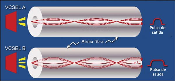
The bandwidth performance of OM4 fiber is guaranteed using the same criteria as OM3 fiber, but to more stringent specifications. Due to a challenge posed when the now familiar VCSEL was first introduced, new measurement methods had to be developed to verify the laser bandwidth of OM3 and OM4 fibers.
Unlike an LED, a VCSEL laser produces a non-uniform energy output; it can change dramatically across the entire output face. Furthermore, each laser fills a different set of light beams in each fiber, and it does so with varying amounts of energy in each beam. Overfilled bandwidth measurements, used to measure LED bandwidth, cannot emulate the operation of a VCSEL.
Standards allow two ways to measure and verify laser bandwidth: the DMD mask method and the EMBc method. Both methods require DMD testing; the difference lies in how the DMD data is used and interpreted.
In DMD testing, small, high-power laser pulses are transmitted through the fiber in small steps across the entire fiber core. Only a few modes are excited at each step, and their arrival times are recorded. The DMD of the fiber is the difference between the earliest and latest arrival times of all modes at all steps.
DMD measurement is currently the only reliable method for verifying the bandwidth required for 10 Gb/s throughput because it is the only method that independently checks all modes across the fiber core. For this reason, industry associations such as TIA/EIA and ISO/IEC have published standards for DMD measurement and DMD specifications for laser-optimized multimode fiber.
The DMD mask method is a simple process that directly compares DMD test results against a set of specifications (called templates or masks) to see if the fiber has the required performance.
This is a straightforward graphical approach to ensuring that data pulses do not extend much beyond the required 10 Gb/s bit period. If the fiber passes these DMD specifications, then you can be assured of at least 2000 MHz-km EMB regardless of which VCSEL you use (provided the VCSEL is compatible).
The EMBc method is a more complex, indirect process. It takes the DMD results and compares them to a set of theoretical “weighting functions” that are intended to represent the launch distributions of all compatible VCSELs.
The DMD results are mathematically combined with each of the 10 weighting functions. This produces 10 different EMBc values, the lowest of which is called minEMBc. The minEMBc value is multiplied by a factor of 1.13 to obtain the fiber's EMB value. If this EMB value is > 2000 MHz-km, the fiber is considered to meet the OM3 requirements and should therefore support 300 meters at 10 Gb/s.
Due to the complex calculations required by the EMBc method, and the fact that the weighting functions only represent a sample of the launch characteristics of many VCSELs that could actually be used in a real system, the EMBc method does not provide the same level of scrutiny of fiber quality and performance as the DMD mask technique. Furthermore, the EMBc method practically ignores the central 0–5 micron (radial) region of a fiber core because the weighting functions place little emphasis on this region.
In conclusion,
OM4 fiber delivers next-generation multimode fiber performance for today's and tomorrow's high-speed applications. With its significantly higher bandwidth, network designers and operators can be confident that multimode fiber will continue to offer the most cost-effective solutions for short-haul applications in data centers and local area networks.
Author:
Tony Irujo, Sales Engineer at OFS


