Class E, Category 6 channels will operate with RJ45 connectivity over UTP, FTP, or S-FTP cabling systems and, according to the standard definition, will provide PSACR up to 200 MHz. Both Class E and F will offer data throughput for frequencies up to 25% higher than 200 and 600 MHz, specifically 250 and 750 MHz, following the same logic used for data throughput up to 125 MHz in Class D and D+.
The Category 6 and Category 7 standards are currently being discussed in standardization committees. Eurodatacab TC WG2 has draft proposals for Category 6 to be submitted to CENELEC, with throughput exceeding that of the ISO/IEC standard as of January. ISO/IEC, for its part, is currently discussing the required connector performance (the main discussion being the choice between 54 dB or 48 dB NEXT), and this will depend on whether or not Cross Connect is used in the channel, as the basic channel model still needs to be ratified. EIA/TIA is also actively working in these areas. Currently, there is no agreement on Class E link performance, except for the clear objective of +ve PSACR at 200 MHz and RJ45 interconnectivity. Both cabling system standards are being written in anticipation of the applications that will require such performance, a situation similar to what occurred with the definition of Category 5 in 1995.
Conclusion:
The IEEE 802.3ab Gigabit Ethernet standard is focused on delivering 1000Base-T over enhanced Category 5 cabling systems. Standardization bodies are developing standards that describe the performance of the cable, components, and system to achieve the required platform.
For a system to meet Category 6 standards, it must comply with all the channel specifications under worst-case scenarios. The most demanding channel (worst-case scenario) consists of 90 meters of horizontal cabling with solid copper conductors in the horizontal run, plus 10 meters of stranded cable in a maximum of three patch cords, and includes a total of four connection points: two at the distribution frame, one at the wall outlet, and one in the horizontal cabling called the consolidation point.
It is not enough for the individual components to be Category 6. The entire set of components (the channel) must also meet performance requirements that are not simply the sum of the individual values but rather have their own specific specifications.
TIA
standards process is dynamic: current standards are being improved, and new standards are being developed to meet market needs.
1. TIA/EIA-568-A-4 Published, Requirements and Procedures for Near-Extreme Crosstalk (NEXT) Testing in the Manufacture of Modular Unshielded Twisted Pair (UTP) Cables: The specifications require the measurement of the crosstalk contribution generated by a patch cord when connected to two test terminals. The parameters are calculated considering the near-extreme crosstalk (NEXT) contribution of the spliced connection to the test terminals and the patch cord requirements.
2. TIA/EIA-568-A-5 Published, Additional Performance Guidelines for 100W Transmission over 4-Pair Category 5e Cable: Category 5e, also known as Enhanced Category 5, is recommended for new installations due to improvements in parameters over the older Category 5. Category 5e refers to channel parameters such as ELFEXT, Return Loss, Power Sum, and Crosstalk, which are required to meet the demands of high-speed, bidirectional applications using all four pairs, such as Gigabit Ethernet.
3. TSB95 Published, Additional Performance Guidelines for 100W Transmission over 4-Pair Category 5:
a) TSB95 includes new channel attributes needed to meet the demands of Gigabit Ethernet installed over Category 5 cable. These new parameters include ELFEXT and Return Loss.
b) TSB95 also includes the methodology for modifying installed Category 5 cabling that does not meet channel requirements to improve performance.
Step 1: Reconfigure the patch connection as an interconnect.
Step 2: Replace the connector at the transition or consolidation point with a Category 5e connector.
Step 3: Replace the connector at the work area outlet with a Category 5e connector.
Step 4: Replace the interconnect with a Category 5e interconnect.
Step 5: Replace the patch cord with a patch cord manufactured for Category 5e to correct return loss faults at low frequencies, such as
4. Proposed Category 6 (ISO Class E): The TIA is working with international organizations to develop the next generation of UTP cabling specifications. Preliminary Category 6 requirements are specified from 1 to 250 MHz and likely represent the best possible performance within the current T568A and 568B configurations for an 8-position, 8-wire modular connector.
Category 7 Proposal (ISO Class F): Category 7 is a fully shielded cabling system with a new female/male connector configuration, likely specified from 1 to 600 MHz. Currently, the TIA has no intention of pursuing further specifications for Category 7. During the recent ISO meeting in Berlin, Alcatel's hybrid RJ-45 connector was selected as the first choice. Siemon's TERA design, distinct from an RJ-45, was selected as an alternative to Alcatel's solution.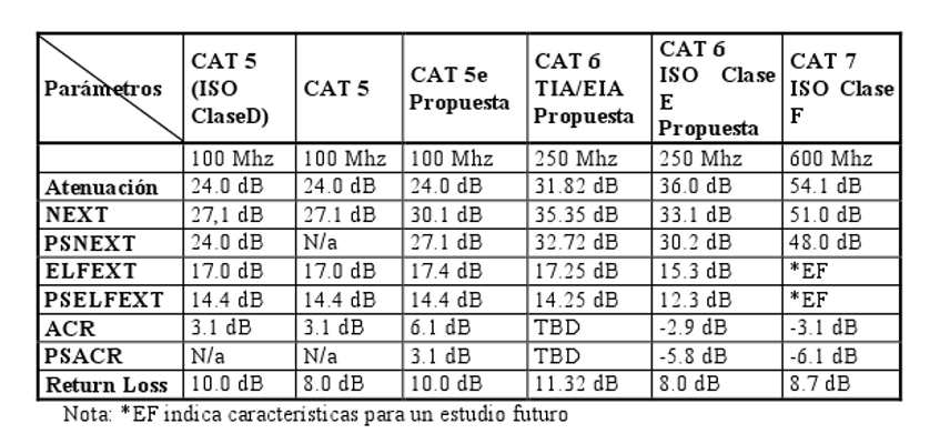
'
CENELEC and
the European Committee for Standardization (CEN) carry out standardization work covering all technical sectors except for the electrotechnical field, which falls under the purview of the European Committee for Electrotechnical Standardization (CENELEC).
The role of both non-profit organizations is to create European standards that foster the competitiveness of European industry globally and contribute to the development of the European single market.
To achieve this, both organizations promote the adoption of ISO and IEC standards.
Objectives
The basic objectives of CEN/CENELEC are as follows:
• To prepare new European standards or harmonisation documents on topics where no international or national standards exist.
• To promote the implementation in Europe of standards developed by ISO or IEC.
Members
The national member committees of CEN/CENELEC are the national standardisation bodies belonging to both the EU Member States (AENOR in Spain) and the EFTA, as well as the Czech Republic.
Structure: The development of European Standards is carried out in technical structures analogous to those of ISO and IEC. CEN/CENELEC normative documents: • European Standards (ENs) that are mandatory for members and are adopted as national standards, approved through a weighted voting procedure. • European Experimental Standards (ENVs): documents prepared by members for provisional application in technical fields where there is a high degree of technological innovation, an urgent need for guidance, or where the safety of persons or property is involved. ISO: The International Organization for Standardization (ISO) is a worldwide federation of national standards bodies from approximately 130 countries, one per region. ISO is a non-governmental organization established in 1947. ISO's mission is to promote the development of standardization and related activities to facilitate the international exchange of goods and services and cooperation in development in the intellectual, scientific, technological, and economic spheres. ISO's work produces international agreements that are published as International Standards. The main reasons are: • Global progress in trade liberalization • Today's free market economies encourage increasingly diverse sources of supply and provide opportunities for expanding markets. The goal is to facilitate trade, exchange, and technology transfer through: • enhanced product quality and reliability at a reasonable price; • improved health, safety, and environmental protection, and reduced losses; • greater compatibility and interoperability of products and services; • simplification for improved usability; • a reduction in the number of models, and thus a reduction in costs; • increased distribution efficiency and ease of maintenance. Users have greater confidence in products and services that conform to International Standards. Conviction of conformity can be based on manufacturers' declarations or on audits carried out by independent bodies. ISO's technical work is highly decentralized, carried out in a hierarchy of some 2,850 technical committees, subcommittees, and active groups. These committees include qualified representatives from industry, research institutes, government, regulatory bodies, consumer organizations, and international organizations. Approximately 30,000 experts participate in the meetings each year. ISO standards are developed according to the following principles: • General agreement • Consideration of the views of all stakeholders: manufacturers, vendors and users, laboratories, governments, and research organizations. • Industry breadth • Global solutions to satisfy worldwide industries and customers. • International market regulation. There are three main phases in the ISO standards development process: • The need for a standard is expressed by an industry sector, which communicates this need to a national member body. The latter proposes the new working article to ISO. Once the need for an International Standard has been recognized and formally agreed upon, the first phase involves defining the technical scope of the future standard. This phase is normally carried out in active groups comprising technical experts from the countries interested in the subject matter. • Once an agreement has been reached on which technical aspects will be covered in the standard, a second phase begins in which the countries negotiate the detailed specifications within the standard. This is the general agreement phase. • The final phase comprises the formal approval of the resulting draft International Standard (the acceptance criteria stipulate approval by ISO members who have actively participated in the standards development process, and 75% approval from all voting members). IEEE The IEEE (Institute of Electrical and Electronics Engineers) has developed a series of standards (IEEE 802.X) that define the physical aspects (cabling, physical and electrical topology) of local area network (LAN) media access control. These standards have been internationally recognized and adopted by ISO in its equivalent ISO 8802.X series. Within the IEEE 802.3 standard is the 100BaseT (Fast Ethernet) standard, which includes different types of segments: • 100BaseT4: each segment consists of 4 twisted copper pairs and RJ-45 connectors. • 100BaseTX: each segment consists of 2 twisted copper pairs and RJ-45 connectors. • 100BaseFX: uses two optical fibers. 100BaseT Application Standards The basic characteristics of the 100BaseT standard are: • A transfer speed of 100 Mbps. • A sublayer (MAC) identical to that of 10BaseT. • Frame format identical to that of 10BaseT. • The same cabling as 10BaseT (compliant with EIA/TIA-568). • Greater fault tolerance than 10 Mbps Ethernet. The 100BaseT (IEEE 802.3) standard comprises five specifications. These define the MAC sublayer, the independent communication interface (MII), and the three physical layers (100BaseTX, 100BaseT4, and 100BaseFX). The MAC sublayer: The 100BaseT MAC sublayer is based on the CSMA/CD protocol. The IEEE 802.3 specification allows a total cable length (including repeaters) of 2.5 km. In the worst-case scenario, the signal propagation delay is the time it takes for the signal to travel twice this distance. The standard allows a signal propagation delay (including repeater delays) of 50 microseconds. As a safety factor, the IEEE decided that the minimum frame size would be 512 bits (equivalent to 64 bytes) and the maximum size 1500 bytes. Reducing the cable length can achieve a higher transfer speed. Since most stations are located a few meters from the concentrators, a limit of 100 meters is appropriate. The distance between the station and the hub is considered reasonable, and therefore, there will only be 200 meters between two stations, and in the worst case, the signal will travel 400 meters. A simple calculation shows that with CSMA/CD, a maximum delay of 50 microseconds, and the same 512-bit frame size, Fast Ethernet can provide a transfer rate of 100 Mbit/s. Fast Ethernet (100BaseT) reduces the transmission time of each bit by a factor of 10, allowing the packet speed to increase tenfold from 10 Mbit/s to 100 Mbit/s. In 10BaseT, the time between frames is 9.6 microseconds, while in 100BaseT it is 0.96 microseconds. Because the MAC layer and frame format are identical to those of 10BaseT, and the 10BaseT error control is also maintained, data can be exchanged between Ethernet and Fast Ethernet without the need for a transmission protocol. Independent communication interface (MII) MII is a specification that defines a standard interface between the MAC sublayer and any of the three physical layers (100BaseTX, 100BaseT4, and 100BaseFX). Because the electrical signals are clearly defined, MII can be implemented internally or externally on a network device. It is common to implement it internally on a network device to connect the MAC layer directly to the physical layer. MII also defines a 40-pin connector that can support external transceivers. By using the appropriate transceiver connected to the MII connector, workstations can be connected to any type of cable. It is capable of supporting speeds of 10 Mbit/s and 100 Mbit/s. A significant difference between 10BaseT and 100BaseT is that the 100 Mbit/s speed does not allow the use of a clock for encoding, as this would violate the limit imposed for use in UTP cabling. The solution to this problem is to use bits in an encoding scheme instead of a clock-based encoding scheme. The Fast Ethernet physical layer can operate over the same variety of media as 10BaseT: unshielded twisted pair (UTP), shielded twisted pair (STP), and fiber optic cable. However, there is one exception: Fast Ethernet does not work with coaxial cable because the industry has discontinued its use for new installations. When upgrading their systems, businesses and institutions are discovering a common theme: the speed of today's Local Area Networks (LANs) will not be able to support the applications of the future. The system of the future is yet to be developed, bringing with it a rich mix of enhanced information through visualization and data modeling, images, graphics, and video. Once limited to a select group of key users, these bandwidth-intensive applications are rapidly becoming commonplace, forcing users to migrate from contemporary systems to newer, faster LANs. In the race to stabilize next-generation LAN technology, Gigabit Ethernet is leading the way. As will be shown later. Later in this report, successfully implementing Gigabit Ethernet over copper will require a complete Category 5 (CAT 5) infrastructure, or preferably an Enhanced Category 5 (CAT5e) infrastructure. Connectors will play a crucial role in ensuring the performance of the cabling infrastructure. Gigabit Ethernet offers a convenient, low-cost alternative for network user migration, as Ethernet technology has proven to be widely adopted. Today, there are over 120 million Ethernet nodes installed worldwide, representing 80% of the installed base of network connections. The original Ethernet standard, IEEE 802.3, issued in 1985, has evolved over time, and several new Ethernet technologies have been added and are covered by 802.3. For example, the 10Base-T (10 Mbps) standard was approved in 1990, and the 100Base-T (100 Mbps) standard was approved in 1995. and its directives support a variety of physical media, including both 50 and 75 AWG coaxial cables, twisted-pair cable, and fiber optic cable. For Gigabit Ethernet applications, two IEEE committees have been working rapidly to develop a new standard. In June 1998, the IEEE 802.3z working group ratified the proposed standard defining Gigabit Ethernet over fiber optic cable. The scope of the standard includes multimode and single-mode fiber and short- and long-band lasers. The 1000Base-T standard for gigabit transmission over copper is still under intensive development. The IEEE 802.3ab working group expects to approve the standard by mid-1999, with implementation planned over Category 5 twisted-pair cable, as defined by TIA-EIA-568-A. This is a critical step in the migration to Gigabit Ethernet, as approximately 70% of the installed base of horizontal cabling systems is Category 5. This market is growing at an average rate of 20% per year. While the goal of both IEEE 802.3zy and 802.3ab standards is to ensure that Gigabit Ethernet operates on existing cabling infrastructure, issuing standards is easier than implementing them. System users are faced with the harsh reality that implementation ultimately depends on them. The selection of components, and in particular, connectors and termination components, will play a vital role in the successful implementation of Gigabit Ethernet.
With the future implementation of Fast Ethernet to the desktop, Gigabit Ethernet deployment will initially be in the backbone, or high-speed interconnections between high-performance workgroups, servers, or computer networks. Backbone applications will operate over fiber optic cable. Although 1000 Mbps transmission over fiber presents some challenges, it will be a relatively simple process.
However, implementing gigabit bandwidth to the desktop over Category 5 UTP horizontal cabling is another matter entirely. It will certainly require careful consideration of the overall cabling infrastructure's performance capabilities, especially the connecting components.
Gigabit Ethernet over Twisted Pair Cable:
Gigabit Ethernet achieves 1000 Mbps by utilizing all four pairs of Category 5 cable. Each pair handles 250 Mbps using a bidirectional transmission scheme simultaneously (fully bidirectional). Because the performance of the connecting components in a fully bidirectional channel is vital, choosing the right manufacturer and components is crucial. In the high-speed world of Gigabit Ethernet, connection elements can make the difference between a successful implementation and a major rewiring project.
Because Category 5 specifications do not define all the electrical parameters for full 1000Base-T support, other components and recommendations have been developed for link and channel performance. Values have been established to characterize the installed base of Category 5 cabling against these parameters. The new channel parameters are:
Channel Return Loss (RL) – the quantification of energy reflection caused by impedance mismatch;
and Equal-Level Far End Crosstalk (ELFEXT) – the quantification of an unwanted signal coupled to a near-end transmitter of a neighboring far-end pair, relative to the quantification of the received signal from the same pair.
Power Sum Equal-Level Far End Crosstalk (PSELFEXT) – The calculation of unwanted signals coupled to multiple transmitters near the far end of a pair, relative to the signal received on the same pair.
Although the installed base provides the basis for generic industry specifications, these must be tested again to verify their ability to support 1000Base-T, as not all Category 5 channels are capable.
Figure 1 shows the parameters proposed by TIA/EIA-568-A, suggesting guidelines for Category 5 that are estimated to support 1000Base-T applications. 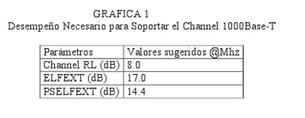
'
Category 5 Enhanced:
The proposed standards for Category 5e recognize the rapid advancements in cabling and component technology and will become the TIA standard for new UTP cable projects designed for 1000Base-T applications. Category 5e channels include the previously mentioned PSELFEXT parameter, with more stringent immunity to near-extreme interference (NEXT) and limits on signal degradation (RL) from multiple interference sources, in fully bidirectional media such as 1000Base-T, and are fully compatible with previous versions of Category 5 channels.
Measurement Parameters:
Wiring Map.
The first condition for successful cable link transmission is that the link must be connected at each of its connections and termination points to provide end-to-end continuity for each wire pair in a link. It is very important for twisted-pair cabling that it be strictly maintained from one end of the link to the other. What allows twisted pairs to transmit at high frequencies with the appropriate integrity, fidelity, and freedom from electromagnetic interference is the fact that the wiring is carefully twisted and the twist ratio is properly maintained along the entire length of the link.
Wiring map testing will discover and report electrical installation failures or wiring defects such as:
• Continuity
• Short circuits between two or more conductors of the tested wiring
• Crossed pairs among any of the tested pairs
• Reversed pairs.
Wiring map testing goes beyond a simple continuity test that ensures each pin of the connector at one end of the link is connected to the corresponding pin at the far end and not to any other conductor. Simple continuity between the pins at one end of the cable to the other is not sufficient for data communication. Furthermore, wiring map testing ensures that the link maintains the proper pairing of conductors.
Length:
The length of a link can be estimated by measuring the electrical length. Field testers measure the "electrical length," which is based on the propagation delay of traveling around the link. Propagation delay is the time it takes for an electrical pulse to travel to the end of the link and back to the tester. A link with an open circuit will reflect the incoming signal back to the tester. The remote tester unit presents an open circuit to the cable pair when its length is measured. This measurement technique is called Time Domain Reflectometry, or TDR. The TDR test method can be compared to a radar pulse. The tester measures the time delay from when this pulse is launched until the reflection is detected.
To convert a time measurement into a distance (the length of the link), you need to know the speed at which the signal travels along the link. NVP, the acronym for Nominal Propagation Speed, expresses how fast electrical signals travel along the cable at the speed of light in space or a vacuum. When we measure the time required for a signal to travel the length of the link, and we know the NVP of the cable, we can calculate the electrical length of the link. Since the signal has traveled along the cable from top to bottom (twice the length), the equation for the length is:
The speed of light in space (or a vacuum) is 300,000,000 meters/second or 0.3 meters/nanosecond. (A nanosecond [ns] is one billionth of a second.) NVP for a Category 5 UTP cable is approximately 69% when an electrical signal travels along a Category 5 cable at approximately 0.2 m/nanosec.
The measurement
of physical length by electronic means creates Some challenges. They are:
• The speed at which electrical signals travel varies slightly depending on the cable segment (even of the same make and model). Differences of 5 to 8% are quite common.
• The shape of a TDR pulse changes considerably as it travels to the end of the cable and back; therefore, it is not always easy to accurately detect the leading edge of the reflected pulse and measure the time delay with extreme accuracy. This can be a problem for the cable tester. The accuracy of the length measurement is influenced by the ability or sensitivity to accurately detect the leading edge of the reflected pulse. The specification for the accuracy of the propagation delay measurement should reflect the skill of a tester.
• All pairs in a 4-pair cable have different twist ratios to improve crosstalk performance. The slightly different NVP results are rated for each pair. The different twist ratios also mean that the lengths of the copper wires are different for each pair.
The combination of these factors is the main reason why the lengths for Individual pairs may yield slightly different results. Differences of 2 to 4% are actually common.
The Pass/Fail Criteria
for structured electrical installations specify that the end-to-end horizontal link shall not exceed 100 meters or 328 feet. This end-to-end link is the link defined as the Raceway in the TIA document TSB-67. When measuring a raceway, the user-end patch and equipment cords shall be used instead of the tester patch cords. The TIA document TSB-67 also defines a model of the link called the Basic Link. The maximum length of a Basic Link is 90 meters (295 feet), plus 4 meters for the test equipment patch cords for a total of 94 meters (308 feet).
Due to the limitations in the accuracy of electrical length measurement, and because length is not the critical parameter, TSB-67 states (paragraph 6.3, page 10): The physical link length calculates the delay, is reported, and is used to make the pass/fail decision. The pass/fail criterion is based on the maximum allowable length of the basic link or channels the NVP uncertainty beyond 10%. The pass/fail limits defined in TSB-67 add an extra 10 percent to the link length specifications to acknowledge the limitations in the accuracy of the electrical length measurement, which is beyond the tester's control. Attenuation, on the other hand, is probably the transmission parameter most affected by the link length.
The accuracy specification defines the worst-case scenario for the length measurement. Typical performance will be much better than this value; this means that if the length measurement yields a value between 97.7 m (100 - 2.3) and 100 m, the tester issues a Pass. Less than 97.7 m constitutes a "flat" Pass.
Insertion Losses:
Electrical signals transmitted over a link lose some of their energy as they travel along the length of the link. Insertion loss measures the amount of energy lost. The insertion loss measurement quantifies the effect of the resistance the link offers to the transmission of electrical signals. Links exhibit more insertion loss for higher frequency signals. Insertion loss will therefore be measured above the applicable frequency range. Insertion loss also increases fairly linearly with link length. Insertion
loss is expressed in decibels, or dB. The decibel is a logarithmic expression of the ratio of output power divided by the input power. The table below demonstrates that the decibel scale is not a linear scale. 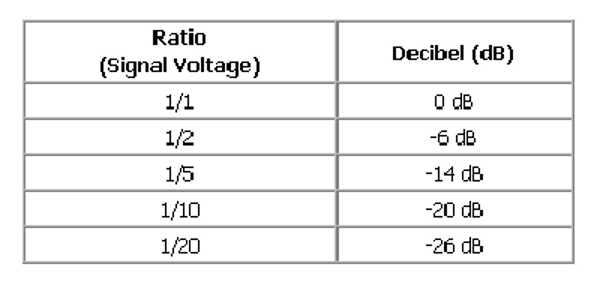
If the power received at the end of the link is reduced to half the power with which the signal was transmitted, the insertion loss is expressed as -6 dB. Insertion loss always yields a negative value. If half the signal were dissipated by the link, the link's insertion loss would be 6 dB. Similarly, in a case where 5 percent of the transmitted energy is lost, the insertion loss would be -6 dB. At the far end of the link, the insertion loss is 26 dB. This means that a small amount of energy has been lost during transmission over the link, and the signal arriving at the far end contains enough energy to be properly decoded by the electronic circuitry in the receiver.
measurement
, the remote unit sends the test signal, which travels the length of the link under test and is moderated by the main unit. Standards such as TIA/EIA TSB-67 define formulas for calculating acceptable insertion loss for an installed link, defined for the Pathway and the Basic Link. TSB-67 publishes a table of acceptable values for the Basic Link and Pathway. The tables define acceptable insertion loss values at 20°C. Insertion loss increases with temperature: typically 1.5% per degree Celsius for Category 3 cable and 0.4% per degree Celsius for Category 4 and 5 cables. Furthermore, Link insertion loss increases by 2 to 3 percent if the cabling is installed in metal conduit, but TSB-67 does not include any special allowance for this effect. The field test instrument will identify the worst-case insertion loss for each wire pair in an installed link and issue a Pass or Fail result by comparing the worst-case value against acceptable insertion loss values. It will report for each wire pair:
If the link is a PASS, then the tester will report:
• The highest moderate insertion loss at the frequency of interest
• The frequency of the highest insertion loss
• The limit of the test at that frequency.
If the result is a FAIL, then the tester will report:
• The moderate insertion loss where the failure occurs
• The frequency at which the failure occurs
• The limit of the test at that frequency.
NEXT:
Crosstalk, or NEXT, is a measure of signal coupling from one pair to another within a UTP/FTP cable. NEXT is a critical transmission performance factor for UTP/FTP links.
The effect of crosstalk is very similar to a noisy transmission line. The receiver cannot distinguish the valid signal from the noisy components induced by crosstalk.
The
cable tester transmits a signal on one pair of the link and measures the magnitude of the signal generated on another pair (the disturbed pair) as a result of crosstalk. This
crosstalk (NEXT) is so named because the crosstalk induced on the disturbed pair at the cable termination point is transmitted from where the disturbing signal originates. 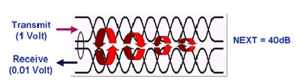
This measurement needs to be repeated for each pair combination for all frequencies of interest.
NEXT is expressed in decibels, or dB. This is the same unit used to express attenuation. However, there is a very important difference. In attenuation testing, it was concluded that the smallest possible dB values were preferred. In contrast, the desired result for the NEXT measurement is the largest possible dB values.
Since the crosstalk disturbance is to be as small as possible, the signal detected on the disturbed pair must be very small. compared to the signal injected into the disturbing pair. Thus, the NEXT ratio should be as small as possible, much less than one. The logarithm of such a ratio yields a large negative number. For example: a 1-volt signal is transmitted on a pair of wires. It also allows us to know that the disturbed signal created by crosstalk on the link is moderated by the tester to 1 mV or 0.001 V. The crosstalk ratio between these signals is 0.001, and the resulting dB value is -60. In practice, the NEXT between these two wire pairs is 60 dB. If, on the other hand, the disturbed signal had been moderated to 8 mV, the ratio would have been 0.008, and the value would have been -42 dB. That is, 42 dB.
NEXT Test Results: TSB-67 defines the formulas for calculating the acceptable NEXT loss for each cable (the Pathway and the Basic Link) over the frequency range. A test instrument The field tester can report the test result in one of two ways: (1) the worst-case NEXT margin or (2) the worst-case NEXT value. The NEXT margin is defined as the difference between the moderate value and the applicable pass/fail limit.
The TIA Essential Element Link measurement must provide a minimum NEXT measurement of 60 dB at 1 MHz, while the pass/fail limit at 100 MHz is 29.3 dB.
Propagation Delay:
The impact of incorrect characteristic impedance values is most accurately measured and represented by the Return Loss quantity.
Return Loss (RL) is a measure of all reflections caused by impedance mismatches along the link and is expressed in decibels (dB).
Return Loss is of particular concern in Gigabit Ethernet applications.
The impedance values at the link ends must match the characteristic impedance of the link. A good match between the Characteristic impedance and termination resistance in the equipment maintain good power transfer across the link and minimize reflections. The return loss measurement varies significantly with frequency. One source of return loss is due to (small) variations in the characteristic impedance value along the cable. The Structural Return Loss (SRL) property summarizes the uniformity in the cable construction. SRL will be measured and controlled during the cable manufacturing process. Another source is caused by reflections within the installed link, primarily from the connectors. The characteristic impedance of links tends to vary from higher values at lower frequencies. Inconsistencies occur predominantly where connectors are present, but can also occur in the cable where variations in characteristic impedance along the cable length are excessive. The main impact of return loss is not in the loss of signal strength, but in the introduction of signal jitter.
The
IEEE 802.3 standards committee has developed a version 1 Gbps Ethernet, called 1000BASE-T, for 100 m of twisted-pair copper.
It is believed that in most situations, the performance of currently installed Category 5 cabling will be satisfactory for 1000BASE-T. Some testers are available on the market, but these existing testers were never designed to measure ELFEXT; the noise floor in the tester is not good enough. New generation testers include: Agilent Wirescope 350, Chiripa DSP-4000, Microtest Omniscanner, and Wavetek LT8600.
Far-End Crosstalk is a measure of the sign coupling of one wire pair to an adjacent pair. Unlike NEXT, the sign of the crosstalk is moderated at the far end of the link.
FEXT is moderated by applying a test sign to a wire pair at one end of the link and measuring the response on another wire pair at the other end. The sign of the crosstalk should be as small as possible, and consequently, the loss should be as high as possible. if possible.
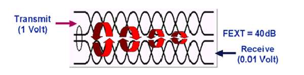
Far-End Crosstalk (FEXT)
is therefore simply the ratio of the measured signal amplitude at the far end of the link to the signal amplitude applied at the local end on a different wire pair. ELFEXT
loss is simply the computed ratio of moderate FEXT loss and moderate attenuation, and is therefore a type of attenuation to Crosstalk Ratio (ACR), or an indication of Sign-to-Noise Ratio (SNR). ACR is the computed ratio of NEXT loss and moderate attenuation. 1000BASE-T carries bidirectional signals on all four wire pairs, and therefore ELFEXT loss is important as a generic transmission parameter.
POWER SUM
values are computed and are often (but not always) specified in LAN systems where more than one wire pair carries a signal in a certain direction. This is the case for 1Gbps Ethernet, but not for 10BASE-T and 100BASE-TX.
Only two pairs are used for either 10BASE-T or 100BASE-TX. One pair is used for transmitting and the other for receiving.
As a simple operating principle, NEXT
ACR is the most important SNR indicator for 10BASE-T and 100BASE-TX technologies, where one wire pair carries the signal in one direction and the other wire pair carries the signal in the opposite direction. ELFEXT is not important for 100BASE-T and 100BASE-TX. 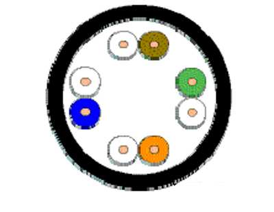
'
'
Gigabit Ethernet uses all four pairs, splitting the 1000 Mbps into four 250 Mbps packets, sending them down the cable, and then reassembling them at the end of the link. So it's quite useful if they arrive at the same time. The tester measures propagation delay to compute the link length, as explained in the section on length. If all signals start at the same time, the pair with the least kink will send the signal faster than the other pairs. One feature that is gaining more attention is the difference in propagation delay for each of the wire pairs. This measurement is called slant delay. One of the requirements to make this possible is that the timing relationship must be maintained from one end of the link to the other. The packets must travel at approximately the same speed at which they were sent. Measuring Slant Delay involves calculating the propagation delay. First, we select the fastest pair; in this example, it's the brown pair. This is the 0ns marking, then we look at the blue pair, there is a 9ns difference (99ns-90ns), so this has a 9ns lag slope and so on.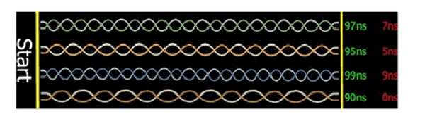
'
CHANNEL
The cable run is the end-to-end transmission path between two points to which equipment on a specific platform is connected. The cable run consists of:
1. Workstation cable
2. Telecommunications outlet/connector
3. Transition cable (optional)
4. Consolidation or transmission point near the work area (optional)
5. Horizontal cable
6. Two interconnects in the telecommunications closet
7. Cord for the equipment in the telecommunications closet
8. Transmission performance requirements for the cable run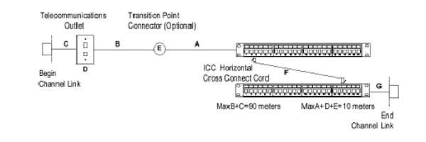
Channel transmission performance requirements:
 '
'
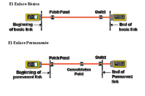
BASIK LINK (Primary Link)
The primary link is a constant component in the cabling of a structure. The primary link consists of:
1. Cord from the field analyzer test equipment to the remote connection
2. A connection at each end
3. Horizontal cable
4. Cord from the main field analyzer test equipment to the local connection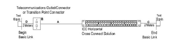
Transmission performance requirements on the Fundamental Link:

Permanent Link
: The term "permanent link" was previously used in ISO/IEC 11801 and EN 50173. In ANSI/TIA/EIA 568-UN, it is equivalent to testing the installation of links in the Basic Link. In the US, the Basic Link will be phased out in favor of the permanent link. This permanent link will be adopted in the new ANSI/TIA/EIA 568-B.