RF systems require power amplifiers (PAs) that deliver high, linear, and efficient output power. As systems move to higher-order modulation schemes, such as 64/128/256 quadrature amplitude modulation (QAM), they must also offer high linearity and efficiency in denser environments with a strict peak-to-average power ratio (PAPR). A new generation of gallium nitride (GaN) PAs on silicon carbide (SiC) monolithic microwave integrated circuits (MMICs) offers a solution to these challenges with the highest power density for generating high, linear output power with high efficiency.
This article delves into the requirements of 5G, satellite communications, aerospace, and defense applications, including the different types of beamforming architectures and how GaN-on-SiC power amplifiers are solving communication challenges in these RF applications.
Opportunities and challenges of RF power amplifiers
The greatest growth opportunities and challenges for RF power amplifiers lie in satellite communications, as well as in emerging 5G communications solutions. NASA has enabled private sector companies to launch thousands of low Earth orbit (LEO) satellites that now orbit the Earth, providing broadband internet access, navigation, maritime surveillance, remote sensing, and other services. These radio frequency applications systematically seek size, weight, power, and cost (SWaP-C) advantages. Large parabolic antennas are being replaced by phased array antennas for satellite communications, which require smaller components for integration, as well as lighter components. High RF power, which is linear with high P1dB and IP3 to reduce distortion, and efficient with high PAE to minimize power consumption, is essential for these RF applications.
5G millimeter wave communications
The new generation of 5G millimeter-wave communication solutions, thanks to their speed, ultra-wide bandwidth, and low latency for broadband communication, is substantially increasing the amount of information that can be shared to support real-time decision-making and other military applications. 5G systems operating in lower frequency bands (below 6 GHz) have been vulnerable to high-power interference signals, but 5G millimeter-wave systems (24 GHz and above) are bringing 5G networks to applications both on and off the battlefield using the millimeter-wave band, which is less susceptible to high-power interference signals. Examples include military sensor networks for command and control data collection and augmented reality displays that enhance situational awareness for pilots and infantry soldiers. 5G will also enable virtual reality solutions for remote vehicle control in air, land, and sea missions. Outside of military environments, 5G will enable various applications such as smart storage, telemedicine, and troop transport.
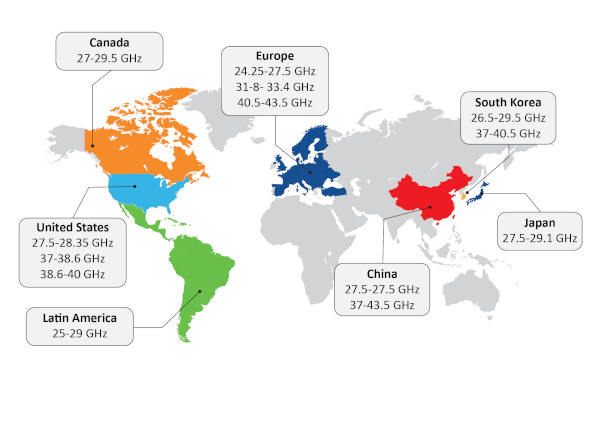
5G millimeter wave frequency bands:
Different countries have different bands for 5G mmWave. In the United States, 28 GHz was the first 5G mmWave band deployed, followed by 39 GHz. China is deploying 5G mmWave in the 24.25–27.5 GHz band and has lagged behind in 5G mmWave adoption.
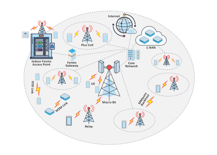
5G network architecture
The 5G network consists of macro base stations and small cells. Macro base stations are connected to the core network via mmWave or fiber optic backhaul links. Macro base stations can communicate directly with user equipment mobile phones or with small cells, which communicate with user equipment mobile devices and provide last-mile connectivity. Picocells and femtocells provide network connectivity within office buildings where the connection may be weak or where there is a high density of users.
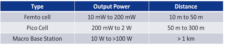
Femtocells are typically installed by the user to improve coverage in a small environment, such as a home office or a dead zone within a building. Femtocells are designed to support only a handful of users and can only handle a few simultaneous calls; they have very low power output, as low as 0.2 watts.
Picocells offer greater capacity and coverage areas, supporting up to 100 users within a range of up to 300 meters. Picocells are typically deployed indoors to improve poor wireless and cellular coverage within a building, such as an office floor or retail space. Picocells can be deployed temporarily in anticipation of heavy traffic in a limited area, such as a sporting event, but they are also installed as a permanent component of cellular mobile networks in a heterogeneous network working in conjunction with macrocells to provide uninterrupted coverage to end users. They have an output power of up to 2 watts.
Macro base stations: These are large base stations that cover an area > km and have an output power of up to > 100 watts.
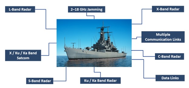
Radar communication application:
Radar systems operate in the L-band from 1 gigahertz (GHz) to 2 GHz for applications including IFF (Identify Friend or Foe), rangefinding equipment, and tracking and surveillance. The S-band (2 GHz to 4 GHz) is used for selective response applications in mode S and for weather radar systems. The X-band (8 GHz to 12 GHz) is used for weather and aircraft radars, while the C-band (4 GHz to 8 GHz) is used for 5G and other communications applications below 7 GHz. 5G mmWave provides the highest bandwidths and data rates, operating in frequency bands of 24 GHz and above. Satellite communications for LEO (Learning Earth Opposite) and geosynchronous communication operate in the K-band, which spans from 12 GHz to 40 GHz.
RF beam formation
The different types of phased antenna beamforming architectures used in these RF applications are:
1> Analog Beamforming
2> Digital Beamforming
3> Hybrid Beamforming
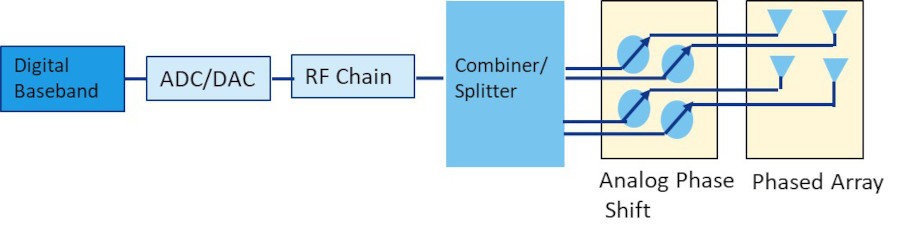
Analog Beamforming
For any phased array, the ideal spacing between elements is half the wavelength of lambda.
The block diagram shows analog beamforming: There are four phased array elements separated by half the wavelength of lambda. For a 30 GHz signal, the spacing between the phased array elements will be 5 mm. In analog beamforming, the phase shifter shapes the beam by changing its phase to create constructive interference for receiving and transmitting the signal by focusing the beam energy in a specific direction. This is all done at the RF frequency, making it more sensitive to interconnect losses. The signal from the phase shifter then passes to the combiner/power divider, followed by an up- and down-converter and an ADC/DAC to the baseband. In this case, for N phased array elements, there is only one digital front end. As seen in the block diagram, for 4 phased array elements, there is only one digital front end consisting of an ADC/DAC. The advantage of this architecture is the smaller number of components and lower power dissipation. However, since the phase shift occurs in RF bands, this type of beamforming architecture is more sensitive to interconnection losses and the complexity of the phase shift.
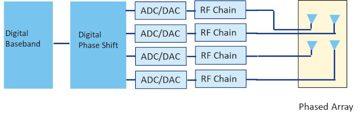
Digital Beamforming
Digital beamforming involves a traditional up- and down-conversion to the baseband frequency, followed by digital phase shifting. This architecture provides greater accuracy because the digital beamforming is performed in the baseband. However, there is one ADC/DAC for each phased array element, resulting in a large number of components and high power dissipation. In this case, for N phased array elements, there are N digital front ends. As shown in the block diagram, for 4 phased array elements, there are 4 digital front ends comprising ADCs/DACs.
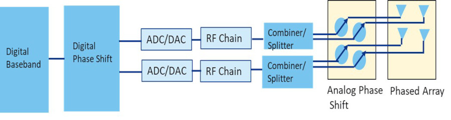
Hybrid Beamforming:
Hybrid Beamforming combines Analog and Digital Beamforming, making it ideal for larger phased arrays to achieve the efficiency of Analog Beamforming with fewer elements, lower power dissipation, and the precision of Digital Beamforming. As shown in the block diagram, for a 4-element phased array, there are 2 digital front ends composed of ADCs/DACs. In comparison, Analog Beamforming only had a single digital ADC/DAC front end, while Digital Beamforming had 4 digital ADC/DAC front ends.
RF signal chain
The figure shows the block diagram of the RF signal chain. At the receiver, the RF signal enters through the antenna, passes through a limiting diode, followed by a switch, and the desired RF frequency is selected via sawtooth filters. The desired signal is then amplified by a low-noise amplifier with an extremely low noise figure to minimize degradation of the signal-to-noise ratio of the received signal. It is then downconverted by a mixer. The local oscillator (LO) signal is generated using discrete PLL components comprising a phase frequency detector, a prescaler to provide the LO frequency to the mixer for conversion to an intermediate frequency (IF), followed by IF-to-baseband conversion for signal processing.
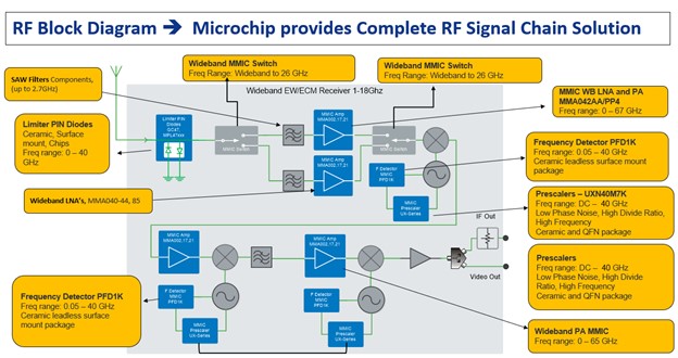
At the transmitter, the baseband signal is converted to IF and then to the desired RF frequency. The RF signal is amplified using a power amplifier for transmission.
Figure of merit RF
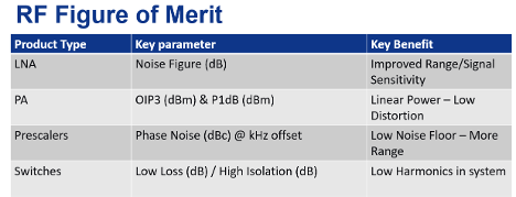
The table shows the RF figure of merit and the advantages of the components used in the RF block diagram.
Power Amplifier (PA) Requirements:
Power amplifiers (PAs) play a critical role in RF transmitter applications. One of the most important requirements for PAs is that they can operate in their linear region to minimize RF distortion. Satellite communication systems using higher-order modulation schemes, such as 64/128/256 quadrature amplitude modulation (QAM), are extremely sensitive to nonlinear behavior. Another challenge is achieving a satisfactory peak-to-average power ratio (PAPR), which is the ratio between the highest power the PA will produce and its average power. The PAPR determines the amount of data that can be transmitted and is proportional to the average power. At the same time, the size of the PA required for a given format depends on the peak power. The FCC's 5G mmWave effective isotropic radiated power (EIRP) requirements include a transmit power of 43 dBm EIRP for mobile terminals and a base station transportable power of 55 dBm EIRP. These and other conflicting challenges can only be overcome with GaN-on-SiC power amplifiers for satellite communications, 5G, aerospace, and defense applications.
Gallium nitride (GaN)-on-silicon carbide (SiC) power amplifiers:
GaN-on-SiC has the highest power density for generating high linear output power with high efficiency. GaN-on-SiC power amplifiers can operate at high frequencies in the Ka and Ku bands from 12 GHz to 40 GHz for satellite communications and 5G, and they offer wide bandwidths, high gain, and improved thermal properties, meeting the requirements of RF applications. Microchip offers GaN-on-SiC RF solutions that meet the SWaP-C requirement for components. The ICP2840 is a flagship device operating in the 27.5-31 GHz band, providing 9 watts of continuous wave (CW) output power and 10 watts of pulsed output power with 22 dB of gain and 22% added power efficiency.
Microchip K-band power amplifiers
The ICP2840 generates a continuous wave output power of 9 W in the 27.5-31 GHz Ka band for uplink frequency for satellite communication, as well as in the 28 GHz 5G frequency band.
The ICP2637 has a wide bandwidth of 23-30 GHz and generates 5 watts of continuous wave output power and is offered in a QFN package as well as in die form.
The ICP1445 generates a pulsed output power of 35 watts in the 13-15.5 GHz frequency band.
The ICP1543 operates in the Ku band from 12 to 18 GHz and generates 20 watts of continuous wave output power.
These power amplifiers (PAs) offer high gain and added power efficiency using GaN-on-SiC technology and meet the Ku/Ka band requirements for 5G, satellite communications, aerospace, and defense applications. GaN-on-SiC, with its higher power density, provides optimal power amplifier solutions for these applications.
Figure 11: Microchip Technology's Ku-Ka band GaN-on-SiC MMIC power amplifiers include the ICP2840, which generates 9 W of continuous wave output power in the 27.5-31 GHz Ka band for uplink.
Author: By Baljit Chandhoke, Product Manager RF Products at Microchip Technology