Introduction
For years, and with increasing frequency, data networks implemented in offices with structured cabling consisting of twisted-pair cables have also been used to power devices designed to receive power through their communication ports, thus avoiding the need for parallel cabling to power these devices.
In June 2003, the IEEE 802.3af standard was approved, establishing the characteristics of PoE equipment and technology. Although other proprietary protocols from some manufacturers pursue the same objective—using the network cable itself to power the connected equipment, i.e., remote power supply—
this technology is now widely adopted, and numerous applications and devices are designed to be powered through their network ports.
Some examples are shown below:
- IP Phones
- IP Cameras
- WiFi Access Points
- Access and Monitoring Systems
- Point of Sale Terminals
- Lighting
- Industrial and Building Automation
The advantages of PoE are:
• Power and data communications over the same cable
• No external power supply required
• Greater control over the device
• The device can be easily moved to another location
• Power management and monitoring via SNMP
• No need to upgrade cabling (Cat5 or higher)
However, with the proliferation of these types of devices, which consume increasingly more energy, the voltage drop introduced by the network cable, and consequently the device's increased power consumption, is a crucial factor to consider, especially when installing new cabling. The characteristics of this cabling can result in a greater or lesser voltage drop, and therefore higher or lower electricity consumption, which ultimately impacts the ROI (Return on Investment). The following sections will analyze specific environments and examples where energy consumption will vary depending on the cabling used.
PoE devices
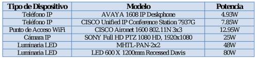 Virtually all PoE protocols, proprietary or not, operate with similar supply voltages, that is, between 36 and 60 VDC, with an average voltage of around 48 VDC. Power consumption can vary considerably depending on the type of device being powered. To illustrate the different examples and scenarios, we will consider various devices with very different power consumption levels.
'
Supporting Calculations
As mentioned previously, all these types of devices allow remote power delivery using twisted-pair network cable (UTP or FTP), 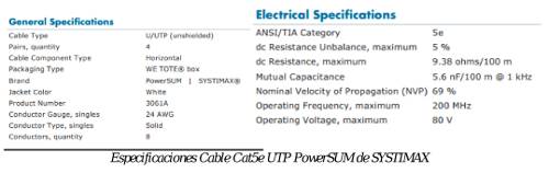
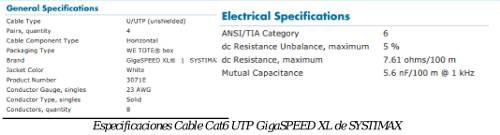 implementing PoE or similar power supply protocols. We will perform the calculations with two types of cables. One will be a SYSTIMAX Cat5E UTP cable, model PowerSUM 3061A (reference 107573545), with a conductor diameter of AWG24 (0.511 mm) and a DC resistance of 9.38 Ω/100 m. The other cable will be a SYSTIMAX Cat6 UTP cable, model GigaSPEED XL 3071E (reference 700216450), with a conductor diameter of AWG23 (0.573 mm) and a DC resistance of 7.61 Ω/100 m.
To determine the voltage drop across the cable, we must consider both its resistance and its length. We will consider an office environment where structured cabling typically has an average horizontal cable length of 50 m, including patch cords at both ends.
Finally, it's important to consider how the power will be injected through the cable; that is, how many pairs of the eight available wires (four pairs) will be used and how. Currently, the most common PoE protocols (802.3af, 802.3at) use two pairs, with one pair used to inject the positive signal (DC+) and the other to inject the negative signal (DC-). A specific example is shown in the following table.
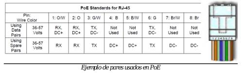 Example of pairs used in PoE: Since both wires of the pair used for power injection are connected in parallel at the power supply and therefore also at the powered device, we must consider that the resistance of the pair will be exactly half the resistance shown by each wire. However, by adding the lengths of each pair to obtain the total DC resistance of the power wires, the resistance to consider will be exactly that shown by each wire, that is, 9.38 Ω/100m for Cat5e cable and 7.61 Ω/100m for Cat6 cable. Since we have considered an average length of 50 m, the DC resistance to consider should be 4.69 Ω for Cat5e cable and 3.8 Ω for Cat6 cable.
Results Presentation- AVAYA 1608 IP Deskphone
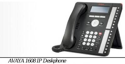
The AVAYA IP phone consumes 4.93W when connected directly to the power supply, without the twisted-pair cable. With the average supply voltage of 48VDC, the device's power consumption will be (P=V*I) 0.1027 amps. Therefore, the current flowing through the cable will be 0.1027 amps, which, across a Cat5e cable with a resistance of 4.69 Ω, would result in a power consumption of (P=R*I²) 0.05W. The Cat6 cable has a resistance of 3.8 Ω, so the power consumption will be 0.04W. Therefore, the total power consumption of the AVAYA IP phone will be 4.98W with Cat5e cabling and 4.97W with Cat6 cabling.
Results Presentation - CISCO Unified IP Conference Station 7937G
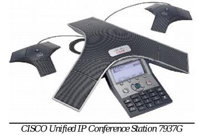
The Cisco IP phone consumes 7.85W when connected directly to the power supply, without the twisted-pair cable. With the average supply voltage of 48VDC, the device's power consumption will be (P=V*I) 0.1635 amps. Therefore, the current flowing through the cable will be 0.1635 amps, which, across a Cat5e cable with a resistance of 4.69 Ω, would result in a power consumption of (P=R*I²) 0.125W. The Cat6 cable has a resistance of 3.8 Ω, so the power consumption will be 0.101W. Therefore, the total power consumption of the Cisco IP phone will be 7.97W with Cat5e cabling and 7.95W with Cat6 cabling.
Results Presentation - CISCO Aironet 1600 802.11N 3x3
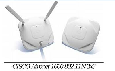
The Cisco WiFi access point consumes 12.95W when connected directly to the power supply, without the twisted-pair cable. With the average supply voltage of 48VDC, the device's power consumption will be (P=V*I) 0.27 amps. Therefore, the current flowing through the cable will be 0.27 amps, which, across a Cat5e cable with a resistance of 4.69 Ω, would result in a power consumption of (P=R*I²) 0.342W. The Cat6 cable has a resistance of 3.8 Ω, so the power consumption will be 0.277W. Therefore, the total power consumption of the Cisco WiFi access point will be 13.29W with Cat5e cabling and 13.23W with Cat6 cabling.
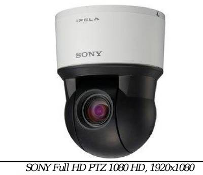
Results Display - SONY Full HD PTZ 1080 HD, 1920x1080
The Sony IP camera consumes 25W when connected directly to the power supply, without the twisted-pair cable. With the average supply voltage of 48VDC, the device's current draw will be (P=V*I) 0.521 amps. Therefore, the current flowing through the cable will be 0.521 amps, which, across a Cat5e cable with a resistance of 4.69 Ω, will result in a power consumption of (P=R*I²) 1.27W. The Cat6 cable has a resistance of 3.8 Ω, so the power consumption will be 1.03W. Therefore, the total power consumption of the Sony IP camera will be 26.27W with Cat5e cabling and 26.03W with Cat6 cabling.
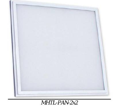
Results Presentation - MHTL-PAN-2x2
LED luminaires that can be powered via twisted-pair cable are also beginning to appear on the market. One of the commercially available solutions, called RedWood, will be discussed later. The MHT luminaire consumes 48W when connected directly to the power supply, i.e., without the twisted-pair cable. With the average supply voltage considered, 48VDC, the consumption of this device will be (P=V*I) 1 amp. Therefore, the current flowing through the cable will be 1 amp, which, across a resistance of 4.69 Ω for the Cat5e cable, will result in a power consumption of (P=R*I²) 4.69W. The Cat6 cable has a resistance of 3.8 Ω, so the power consumption will be 3.8W. That said, it can be concluded that the total consumption of the MHT luminaire will be 52.69W if the wiring system is Cat5e and 51.8W if the wiring system is Cat6.
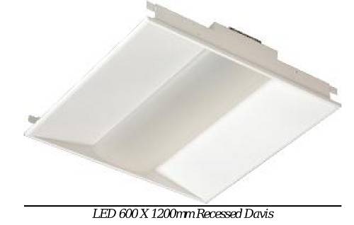
Results Display - LED 600 X 1200mm Recessed Davis
The DAVIS luminaire consumes 80W when connected directly to the power supply, without the twisted-pair cable. With the average supply voltage considered, 48VDC, the current draw of this device will be (P=V*I) 1.67 amps. Therefore, the current flowing through the cable will be 1.67 amps, which, with a resistance of 4.69 Ω for the Cat5e cable, will result in a power consumption of (P=R*I²) 7.83W. The Cat6 cable has a resistance of 3.8 Ω, so the power consumption will be 6.35W. Therefore, it can be concluded that the total power consumption of the MHT luminaire will be 87.83W with Cat5e cabling and 86.35W with Cat6 cabling.
Annual Energy Savings
As calculated in the previous sections, the greater resistance of Cat5e cables compared to Cat6 cables results in additional power consumption. This additional power is approximately 20%. Let's now assess the potential savings of using a Category 6 system over a Category 5e system. To do this, we must consider the difference in power consumption between the two cabling solutions, the time frame for the calculation, the energy cost, and the number of devices. The formula summarizing all of this would be something like the following:
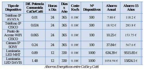 ((Difference in Power Consumption by Cabling) x (hours per day x days per year) / 1000 (to convert to KW)) x (Cost of kWh) x (Number of Devices) Device Type Difference in Power Consumption Cat5e/Cat6 Hours x Day Days x Year Cost kWh Number of Devices Annual Savings Savings over 15 Years Savings over 15 Years AVAYA IP Phone 0.01 24 365 €0.18 500 €7.88 €118.20 CISCO IP Phone 0.024 24 365 €0.18 500 €18.92 €283.80 CISCO WiFi Access Point 0.065 24 365 €0.18 100 €10.25 €153.75 SONY IP Camera 0.24 24 365 0.18€ 100 37.84 € 567.6 € MHT LED Luminaire 0.89 12 330 0.18€ 1000 634.39 € 9515.85 € DAVIS LED Luminaire 1.48 12 330 0.18€ 1000 1054.94 € 15824.1 € Energy Savings between Cat5e and Cat6.
Conclusions
The table above shows how, as the power consumed by devices increases, the savings become much more significant. There are more and more devices powered by PoE, and their power consumption is constantly growing. Considering the average lifespan of structured cabling installed in offices, which is typically over 15 years, the slight initial investment required to install Cat6 instead of Cat5e is recouped in just a few years—shorter the more PoE devices there are and the higher their power consumption. Furthermore, PoE technologies are increasingly designed to power higher-power devices. For example, the IEEE is currently studying the possibility of sending currents between 800 and 1000 mA per pair (up to 4 Amps per cable), so the differences in voltage drops between the various cable categories could become increasingly significant. It is also very important to consider the heating of the cables, especially because with the increase in temperature the attenuation of the cable will also increase and, therefore, links of length close to 90m may stop working and have loss of link due to the excessive attenuation caused by the temperature.
LED Power Supply and Lighting Management Platform - RedWood
Redwood is a platform for powering, controlling, and managing LED lighting using structured cabling. Lighting systems that can be monitored and controlled typically have one or two additional circuits besides the power supply for this purpose.
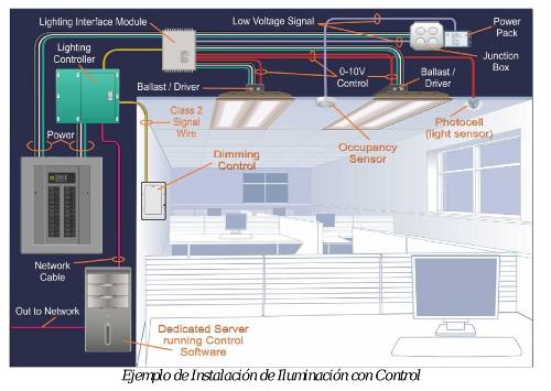
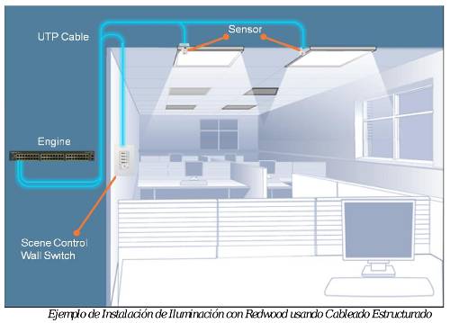 With Redwood, the wiring for powering, controlling, and managing the luminaires will be a single, structured cabling system of Cat5e or higher.
Example of a Redwood Lighting Installation using Structured Cabling
The Redwood solution consists of the following elements:
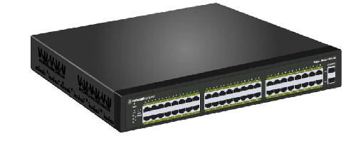 - Redwood Engine. This is the power supply device that also has the ability to measure the consumption of each port/luminaire and the software for managing the platform.
'
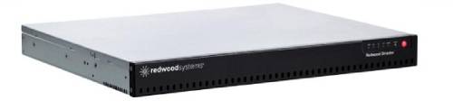 - Redwood Director. It has a BACnet port and an API that allows the platform to be integrated with other building facilities such as the air conditioning system, meeting room management, or integration with security systems.
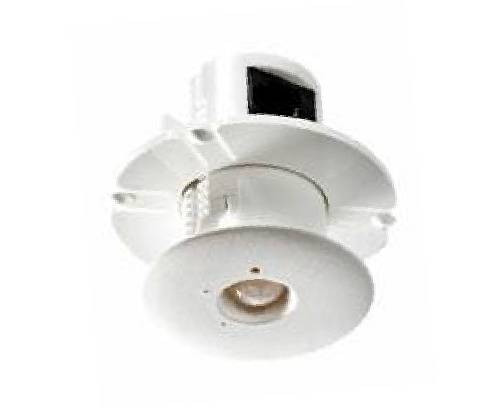 - Redwood Sensor. A sensor capable of measuring temperature, light levels, and detecting presence can be installed on the same wiring that supplies power and manages the lights. - Redwood Adapter. This sensor has identical characteristics to the one mentioned above, but also acts as a gateway, as described in the following section.
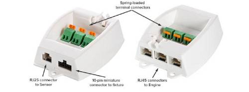
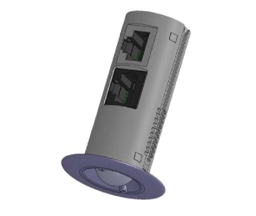 - Redwood Gateway. In order to detect and activate each of the luminaires, a Gateway is required which will be factory programmed with the operating voltages/currents of the luminaire it serves.
 - Redwood Scene Control Switch: In some environments, such as meeting rooms, a scene controller can be incorporated so that, with the push of a button, a pre-configured scene can be created to adapt the room's lighting to the current needs. This same device allows you to turn all the lights in the room on and off, as well as manually adjust their intensity.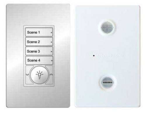
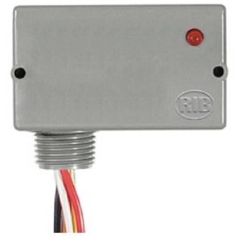 - Redwood Relay: It is also possible to control lights powered by 230 VAC. For this, a relay can be used, which will be controlled via the Gateway to which it is connected.
The following diagram shows a detailed breakdown of the solution's components. The luminaires will not be Redwood brand but rather from standard luminaire manufacturers. While luminaires already exist that are designed for integration with the platform, any luminaire powered by direct current (DC) could theoretically be integrated.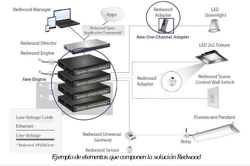
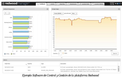
The power supply, control, and management capabilities of this platform offer energy savings or reductions in lighting consumption ranging from 70% to 90% compared to the energy cost of a similar lighting system based on fluorescent lighting. The software platform for controlling and monitoring the luminaires resides on both the Redwood Engine and the Director, and can be accessed either locally via the console port or remotely, if the Engine/Director is networked, using a standard web browser. This software allows for measuring the energy consumption of the entire installation or by specific zones, as well as measuring the temperature in areas where sensors have been installed. It also allows for individual control of each luminaire or a predefined zone. The following image shows an example of this software.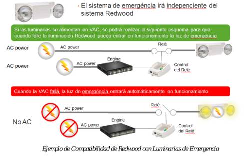
 The system is also compatible with the emergency lighting required in most public buildings. To achieve this, the emergency light will have its own VAC power circuit but will pass through a relay controlled by the Redwood platform, so that if the VAC power supply fails, the relay will open or simply no VAC will reach the emergency lights, thus activating the emergency light.
By Alberto Martínez, Technical Manager, Spain & Portugal, CommScope Enterprise