Oscilloscopes are subject to various signal integrity problems, such as distortion, noise, and loss. Results obtained using oscilloscopes with poor signal integrity can increase risk related to development cycle times, manufacturing quality, and component selection. To minimize risk, engineers should evaluate and select oscilloscopes with high signal integrity attributes.
Oscilloscopes with superior signal integrity attributes provide better representation of the signals under test, both in terms of accurate waveform representation and measurements derived from those waveforms. But what criteria can you use to evaluate an oscilloscope's signal integrity attributes? Here are five metrics you should use to quickly determine the quality of an oscilloscope's signal integrity:
1. What is its resolution?
2. What is its vertical scaling range?
3. What is its noise level?
4. How flat is the frequency response?
5. What is the ENOB (effective number of bits) of the oscilloscope?
It's worthwhile to briefly review each metric and how to determine the value of a specific oscilloscope to improve our evaluation capabilities. For high signal integrity, the oscilloscope should score highly across all criteria. If it performs well in one criterion but poorly in others, the signal integrity will not be optimal.
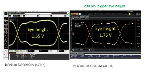
Figure 1. Two oscilloscopes with the same bandwidth and identical configuration obtain different eye height data when connected to the same signal. Two signal integrity attributes can explain why the measurements differ. The oscilloscope on the right has more noise (thicker trace) and greater frequency response variation, which creates some distortion in the waveform seen at the bottom of the eye. The Infiniium S-Series oscilloscope on the right has 50% less noise and a flatter frequency response, resulting in better measurement results.
Resolution
The higher the ADC bit count, the greater the oscilloscope's resolution. The ADC bit count is listed in each manufacturer's datasheet.
Resolution is the minimum quantization level determined by the oscilloscope's analog-to-digital converter (ADC). An oscilloscope ADC with 8-bit resolution can encode an analog input into 256 different levels (2⁸) or 256 Q (quantization) levels. A 10-bit ADC offers four times the resolution of an oscilloscope with an 8-bit ADC. Similarly, a 12-bit ADC provides four times the resolution of a 10-bit ADC.
The ADC acts on the full-scale vertical value of the oscilloscope. For current and voltage measurements, the absolute resolution levels are a function of the full-scale scaling. If the user sets the vertical setting to 100 mV per division on an oscilloscope with eight vertical divisions, the full display corresponds to 800 mV (8 divisions * 100 mV/div), and the Q-level resolution is equal to 800 mV divided by 256 levels, or 3125 mV.
If a higher sampling rate is available and an analog input is used to avoid aliasing, oscilloscopes often offer another mode called "high-resolution mode." Oversampling techniques combined with DSP filters can increase vertical resolution. Manufacturers often present this increase in "resolution bits." To use this technique, an ADC designed with a higher sampling rate than the hardware bandwidth required for a given measurement is needed.
To achieve the best resolution, engineers should use the most sensitive vertical scaling setting while keeping the waveform on screen. Reducing a signal so that it occupies only half the vertical display reduces the number of ADC bits used by one bit. Reducing the signal to occupy a quarter of the vertical display reduces the number of ADC bits used by two bits. To utilize all the oscilloscope's ADC bits, zoom in on the waveform to fill the entire vertical scale.
Vertical Scaling Range:
The combination of the ADC, the oscilloscope's input architecture, and the probe used determines the minimum level of vertical scaling the oscilloscope can achieve. There is a point beyond which each oscilloscope family cannot reduce its internal vertical scale, no matter how much the oscilloscope's controls allow the user to set a lower value. Manufacturers often refer to this as the point at which the oscilloscope uses software boost. Setting the oscilloscope's vertical scale to a lower value only increases the displayed signal. In fact, it does not increase the resolution, as the user might expect.
Oscilloscope manufacturers are not required to list the minimum hardware scaling value in their product datasheets. If it is not listed, ask your manufacturer what the minimum full-scale vertical scaling supported by the hardware is and whether there are any bandwidth limitations at low vertical values.
Most traditional oscilloscopes use software boost below 10 mV/div. Additionally, some oscilloscope manufacturers limit bandwidth when vertical values are low (below 10 mV/div). This is because the noise at the input of their oscilloscopes is so high that it would be virtually impossible to view small signals using the full bandwidth. Several newer oscilloscopes support hardware scaling of signals as low as 10 mV to 16 mV.
Noise
Noise is the biggest enemy of resolution, sometimes even more so than the minimum Q levels that limit an oscilloscope's ability to utilize its resolution. Noise can come from various sources, including the oscilloscope's input, the oscilloscope's ADC, and the probe or cable connecting to the device. Having an oscilloscope with low noise (high dynamic range) is essential for seeing small currents and voltages or for observing small changes in large signals. You won't be able to see signal details smaller than the oscilloscope's noise level. Noise affects both horizontal and vertical measurements. Measured values are subject to a maximum deviation from the oscilloscope's noise level. If noise levels exceed the ADC's quantization levels, users won't be able to take advantage of the ADC's additional bits.
Most oscilloscope manufacturers characterize the noise of each specific model and include that value in the product datasheet. If not, you can determine it yourself in a matter of minutes. Disconnect all front panel inputs from the oscilloscope and set the oscilloscope's input path to 50 Ω. Set a good amount of acquisition memory, for example, 1 Mpt, with a high sampling rate to ensure it's working with the oscilloscope's full bandwidth. The thicker the waveform, the more noise the oscilloscope generates internally. Each oscilloscope channel will exhibit a unique noise quality for each vertical setting. Take an AC measurement of Vrms at each vertical setting to quantify it. Now it's easy to compare the noise of two different oscilloscopes at 100 mV/div, for example. In some oscilloscope categories, the best oscilloscope will have about three times less noise than the worst oscilloscope in the same category.
Frequency response
Analog filters are not perfect. In an ideal world, all oscilloscopes would have a flat frequency and phase response. Flat frequency responses indicate that the oscilloscope treats all frequencies equally. Oscilloscopes characterize both the magnitude and phase of the response. In any family of oscilloscopes, the analog filters used for the oscilloscope input always introduce some deviation in magnitude and phase, resulting in some signal distortion. Some oscilloscopes rely solely on analog input filters to determine the frequency response, while others have frequency responses determined by a combination of analog inputs and DSP correction filters. Correction filters smooth out imperfections in the frequency response to achieve a flatter magnitude and phase response than that obtained using only the analog filter. Most high-end oscilloscopes include correction filters to create a flatter, more uniform frequency response, while lower-end oscilloscopes typically omit them due to their cost and complexity. Oscilloscope manufacturers don't usually publish frequency responses in datasheets, but they will provide them upon request. It's important to obtain a trace of the specific bandwidth being analyzed.
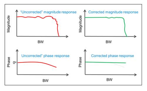 Figure 2. Natural analog filters are not perfect. Oscilloscopes with high signal integrity incorporate DSP correction filters to perform compensation, resulting in a flatter, more uniform magnitude and phase response.
ENOB (number of effective bits)
ENOB is an IEEE standard and can be used as a metric to evaluate the quality of an oscilloscope's ADCs, digitizers, and signal integrity. Unlike other metrics described that focus on a single attribute, ENOB combines vertical and horizontal attributes. How is ENOB measured? ENOB is measured as a fixed-amplitude sine wave using a frequency sweep. ENOB is calculated by subtracting the best theoretical sine wave from the measured waveform. If the ENOB value is not listed on the product data sheet, manufacturers will provide it upon request for a specific model number. The ENOB value will be lower than the oscilloscope's ADC bits. Although a specific ENOB value is given for ease of communication, ENOB values vary across the oscilloscope's specified bandwidth range, as shown in Figure 3.
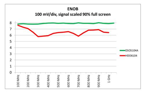 Figure 3. While manufacturers may specify a single ENOB value, ENOB is actually a series of traces, with one curve for each vertical setting. The figure shows ENOB traces for two oscilloscopes, both set to 100 mV/div and with a bandwidth specification of 1 GHz. Interestingly, the Keysight Infiniium DSOS104A oscilloscope with a 10-bit ADC offers a higher ENOB than the LeCroy HDO6014 model with a 12-bit ADC. This is because ENOB incorporates a range of horizontal and vertical attributes and therefore provides a better metric for overall signal integrity.
Author: Joel Woodward. Keysight Technologies