It also allows the use of smaller antennas. The increased bandwidth combined with higher operating frequencies presents significant challenges for RF engineers when testing satellite systems, modules, and components.
This article describes, firstly, the satellite applications where power measurements are typically required and, secondly, the important factors to consider when selecting power meter and sensor solutions. It also explains how these solutions contribute to simplifying your work and improving the accuracy, reliability, and coverage of your tests.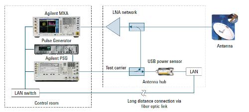 2.0 Satellite Applications:
Power measurements are essential when conducting satellite-related tests. As an example, the following sections describe three main applications where power measurements are necessary.
• Continuous monitoring of received power at a satellite antenna tower. Due to the large distance between satellites and ground stations, the signal received at ground stations is usually very weak (less than -100 dBm). This can worsen under certain weather conditions, such as cloud cover, humidity, or extreme temperature ranges, which cause high atmospheric attenuation. Antenna misalignment can also lead to power degradation. Continuous monitoring of remote signals is important to ensure that the received signal-to-noise ratio is high enough for the communications link to function correctly. To ensure accurate measurements, a spectrum analyzer combined with a power sensor can be used.
• Satellite manufacturing testing. Before launching a satellite into space, it must undergo meticulous testing in a thermal vacuum chamber to simulate the various extreme environmental conditions found in space. The tests, which last several months, are conducted 24/7. During this time, the chambers cyclically alternate between high and low temperatures and other environmental conditions. Ports on the side of the chamber allow various test equipment on multiple racks to be connected to the satellite inside the chamber. Power measurement is crucial during the testing phase because it monitors the output power of the transmitters and detects instabilities, power spikes, and glitches. Up to 20 power meters and sensors can be connected simultaneously to the satellite to conduct comprehensive testing related to the Ku and Ka bands. Power measurements are polled approximately once per second to ensure stability. A continuous-band chart recorder is connected to the power meter's recorder output to log the data. If the transmitted power begins to fluctuate, the test software shuts down the satellite to prevent damage. Given that testing costs are around $1 million per day, ensuring accurate and reliable measurements is essential.
• Satellite component testing. Traveling-wave tube amplifiers (TWTAs) and repeaters are essential components of satellite communication systems and require precise power measurements. Transponder-wave amplifiers (TWTAs) are used as amplifiers in satellite transponders when the input signal is very weak and a higher output signal is required. TWTAs are commonly used in satellites because of their wide frequency coverage and high power capacity. To ensure that the TWTAs can generate sufficient output power for the satellite transponder to function correctly, their output power must be tested. Repeaters, on the other hand, are used to amplify and retransmit the signal at a different frequency. Repeaters act as receivers, frequency translators, and transmitters. Repeaters, sometimes called "transponders," typically consist of a low-noise amplifier, a mixer or local oscillator, and a high-power amplifier, such as a TWTA. Because the receiver and transmitter in repeaters operate simultaneously and in close proximity, thorough testing is necessary to ensure that the transmitter does not interfere with the receiver.
3.0 Important Factors When Selecting Power Meters and Sensors
Due to the wide variety of requirements presented above, it is necessary to carefully study all relevant factors in order to select the appropriate power meter and sensor. Some of the most important factors are described below:
• Frequency range. Many satellite communication systems operate at microwave frequencies, such as the X-band (8 to 12 GHz), Ku-band (11 to 15 GHz), and Ka-band (18 to 40 GHz). It is important to choose a power sensor capable of covering these high frequencies.
• Long-term remote monitoring. In satellite applications where remote monitoring of a satellite antenna tower or testing of a satellite in a vacuum chamber is required, the distance between the control room and the actual measurement point can be several tens of meters. Conventional power meter and sensor solutions are limited by a maximum cable length of approximately 60 meters. In the case of USB power sensors, their specific length limit is five meters. However, a commercial network USB hub or extender can be used to extend the maximum cable length to 90 meters (depending on the hub or extender's specifications). Furthermore, the chosen sensor should offer long-term data logging for up to one year and be able to alert the user when power limits are exceeded. Satellite RF amplifiers generate several tenths of a kilowatt of RF power, so to prevent malfunctions or irreparable damage, it is important to turn off the amplifiers when power levels exceeding the limit are detected.
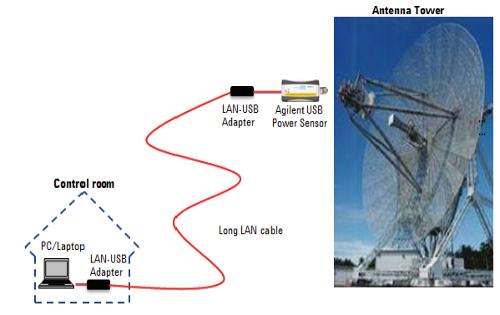 Figure 2. The maximum cable length of a USB power sensor can be extended to 90 meters using a network USB hub or extender.
• Zeroing and calibration. During remote monitoring of a satellite antenna tower or testing in a vacuum chamber, the sensor is not always accessible. Therefore, the sensor must be capable of performing accurate long-term testing without human intervention. When selecting the right power sensor, features such as internal zeroing and calibration, and excellent long-term desynchronization performance, should be considered. Sensors with internal zeroing and calibration integrate a DC reference source and switching circuit, allowing users to perform zeroing and calibration with the sensor connected to a device under test (DUT). This eliminates the need to connect and disconnect the sensor to an external calibration source, reducing test time, measurement uncertainty, and connector wear. The sensor can remain connected to the satellite terminals for months without human intervention.
Multi-channel operation is also crucial. Due to their compact form factor without a front panel, USB power sensors often include proprietary software. It is important to choose a USB power sensor capable of monitoring and displaying measurements from multiple sensors (up to 20) simultaneously. This allows users to continuously monitor numerous satellite transmitters at the same time and perform cross-channel mathematical operations, such as ratio and delta calculations. With this solution, there is no longer any need to dedicate time or effort to developing custom software to monitor multiple transmitter outputs.
• Performance at varying temperatures. During rigorous testing in the vacuum chamber, the satellite will be subjected to extreme temperatures. It is crucial that the power sensor incorporates temperature-compensated calibration factors to ensure measurement accuracy across a wide temperature range. The correction factors are stored in the sensor's memory to correct for variations due to frequencies, power levels, and temperature. The sensor's integrated thermistor detects changes in ambient temperature, so the appropriate correction factor is applied to compensate for any temperature-related desynchronization. This ensures that the USB power sensor can maintain high accuracy across a wide temperature range.
• Measurement types. For routine monitoring of satellite performance, simple average power measurements available on most power meters or sensors are sufficient. However, an integrated data logger output can be very useful for archiving measurement results. The recorder output can be activated to provide a voltage proportional to the average power measured, ranging from 0 to 1 V. This allows the user to connect a plotter or continuous-band chart recorder to print a history of the measurements. This feature is very useful for troubleshooting.
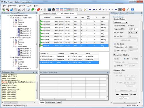 Figure 3. The multi-list display format of Agilent's Power Analysis Manager N1918A software supports more than 20 simultaneous USB power sensors.
4.0 Conclusion
Satellite testing, whether of components, modules, or the entire system, is becoming increasingly complex and demands high precision and reliability. Defects and non-compliance with specifications can have serious consequences and, in some cases, endanger lives. Therefore, manufacturers must offer high-quality products with maximum reliability. Effective satellite testing requires combining high-performance test equipment with comprehensive testing to meet demanding customer expectations. With 50 years of experience manufacturing high-quality power measurement tools, Agilent offers a wide range of power measurement equipment suitable for accurate and reliable satellite testing. For more information on Agilent's recommended power measurement solutions for satellite testing, please see the application note on the Power Measurement Tips and Tricks page (www.agilent.com/find/rfpowertips).
Sook Hua Wong (
Product Planner, Agilent Technologies, Inc.