
 New, advanced modulation formats have recently emerged in the field of optical communication systems. Specifically, the use of DPSK (differential phase-shift keying) modulation has been shown to improve the performance of long-distance optical communication links. Compared to the traditional OOK (on-off keying) intensity modulation format, DPSK provides a 3 dB improvement in receiver sensitivity while also being more tolerant of nonlinear effects, particularly phase-shift keying in DWDM systems.
While NRZ (non-return-to-zero) intensity modulation is a low-cost option, the greater transmission distances and improved spectral efficiencies achieved with newer modulation formats will allow for increased system profitability in the future. In particular, it is worth highlighting that DPSK modulation represents the fundamental principle for doubling transmission capacity without incurring a power penalty due to chromatic dispersion or polarization modal dispersion (PMD).
DPSK Modulator and Demodulator Architectures.
The DPSK signal, which carries information by means of the phase difference between adjacent symbols, can be generated using different methods. Among the most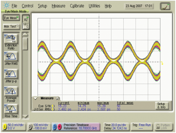 basic are the use of a phase modulator biased to Vp, a dual-arm Mach-Zehnder modulator in a push-pull configuration with two amplifiers, or a single chirp-free Mach-Zehnder modulator biased to 2Vp to achieve a full phase shift. The main disadvantage of direct phase modulation techniques is that they introduce chirp. Other DPSK transmitter schemes use an architecture with two Mach-Zehnder modulators in parallel.
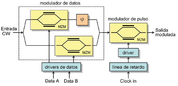
Figure 1 shows the schematic diagram of a possible DQPSK (differential quadrature phase shift keying) modulator. The data is encoded on the optical carrier using four distinct phase states. Since each transmitted symbol includes two bits of information, the symbol rate is reduced by a factor of 2, allowing for high spectral efficiency. The SHF 46213A is a parallel modulator that converts two electrical data streams (I and Q) of up to 22 Gbit/s into a single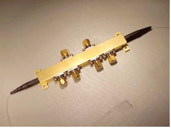 optical data stream of up to 44 Gbit/s (22 GBaud). Both electrical data signals modulate the optical carrier with a phase difference of π/2 using separate chirp-free Mach-Zehnder modulators. As a preliminary step to the recombination of the two optical streams, the Q component undergoes an additional phase shift of π/2 to achieve the four different phase states of the transmitted signal. The I and Q data channels can be independently activated or deactivated, allowing the generation of DPSK or DQPSK signals. Finally, the third Mach-Zehnder modulator shapes the output optical pulses to select between NRZ or RZ signals. As an example, the eye diagram of a 21.4 Gbit/s RZ-DQPSK signal captured with a DPSK receiver (SHF 47211A) is shown in Figure 2. The same company also offers another version of a DQPSK optical transmitter (SHF 46214A) that can reach speeds of up to 100 Gbit/s, although in this case it is NRZ. Another example of a modulator is that of the company COVEGA. It is a (D)QPSK modulator based on two Mach-Zehnder interferometers, which also allows the generation of single-sideband suppressed-carrier (SSB-SC) signals. The appearance of this device can be seen in Figure 3.
 Furthermore, the use of resonant micro-ring structures has recently been proposed for the implementation of DPSK modulators and demodulators. Until now, such devices had been used to construct intensity modulators, switching the optical output power between "on" and "off" states by shifting the cavity's resonance peak. This shift can be achieved by varying the carrier density and, consequently, the refractive index of the ring, by applying a certain electrical voltage, or by injecting carriers.
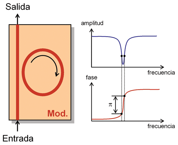
The ring radius is typically on the order of microns, and the cavity quality factor is around 10,000. The basic operating principle is explained below. When the resonant peak shifts, the continuous-wave optical signal can undergo a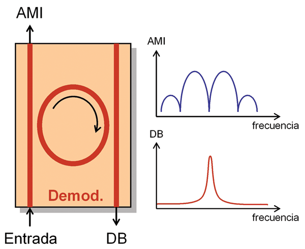 phase change of up to p radians along the central region of the phase profile, as shown in Figure 4. The only precaution to take is that both phase states provide the same output power throughout the bit duration, thus achieving NRZ-DPSK modulation. In any case, power nulls will occur during bit transitions due to the cavity's resonant response, in addition to frequency chirps caused by the rapid phase changes. Fortunately, since both effects occur simultaneously, the problem is minimized.
Now, if the goal is to demodulate a DPSK signal, a structure very similar to the one shown in Figure 5 can be used. The main difference lies in the presence of a new waveguide positioned symmetrically to the previous one. In this case, the resonant structure acts as a bandpass filter, producing two types of signals at the device's two ports:
DB (duobinary) and AMI (alternate-mark inversion). Both signals, DB and AMI, are then photodetected individually and electronically combined to obtain a balanced detector for DPSK signals. Commercially available DPSK demodulators operate similarly, although in that case, the demodulator typically uses a delay-line-based interferometer.
Finally, it is worth noting that Kylia has recently launched a new line of ultra-fast DPSK demodulators, whose piezoelectric actuator ensures a time constant of 0.1 s for compensating for very rapid variations in signal frequency, compared to the 5 s offered by the competition.
Format Converters.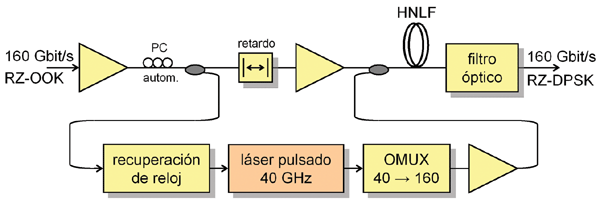 In the future, the increasing use of DPSK modulation in optical networks will necessitate the coexistence of different modulation formats, making it commonplace to convert signals between them. However, as signal bit rates increase, there is a growing interest in performing these format changes within the optical domain, avoiding any optoelectronic conversion or demodulation process. Research in this area has been ongoing in recent years, and several modulation format converter architectures have been proposed. Below,
we will examine an example of one such architecture. Specifically, it is an all-optical OOK/DPSK online converter capable of handling high-speed signals.
The architecture of this converter is shown in Figure 6 (C. Schmidt et al., ECOC'06). The key element is a 630 m long highly nonlinear fiber (HNLF), which operates simply. The OOK data pulses arriving at the converter induce phase shifts on a locally generated pulse train (LPT) at a different wavelength, obtained from the recovered clock signal. A logic "1" in the OOK signal produces a nonlinear phase shift of XPM. At the output, an optical filter removes the input wavelength. It should be noted that this converter operation inverts the signal logic, so a decoder will be required at the receiving end. The converter has been successfully demonstrated in HHI laboratories using 160 Gbit/s RZ-OOK signals over fiber links up to 320 km, suggesting a promising future for this type of architecture.
Francisco Ramos Pascual. PhD in Telecommunications Engineering.
Full Professor at the Polytechnic University of Valencia.

