
 Optical signals undergo multiple degradations during their transmission path, caused by phenomena such as chromatic dispersion, polarization modal dispersion (PMD), nonlinear effects, and noise. These degradations become more significant as fiber length, bit rate, and number of channels increase. Long-distance optical networks therefore require signal regeneration mechanisms to restore signal quality and ensure reliable, error-free transmission. To date, signal regeneration has been performed electronically, that is, by photodetecting the signal as a preliminary step to regeneration and subsequent modulation of the optical carrier with a new transmitter. However, compared to optical-to-electrical-to-electrical converters, optical regeneration technology allows for lower power consumption and a more compact device size, while also providing protocol and signal format transparency. This series of articles will discuss the current state of optical regeneration technology, especially type 3R, which is characterized by three types of processing: Re-amplification, Re-shaping, Re-timing.
3R Optical Regenerators
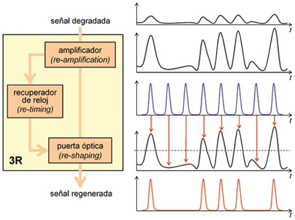
Figure 1 shows the block diagram of a 3R regenerator along with the signals present in each stage. As mentioned earlier, the abbreviation 3R refers to three different types of functions. The first function (re-amplification) is performed using optical amplifiers. The amplification process is independent of the bit rate and data format, and several WDM channels can be amplified simultaneously. However, crosstalk is also amplified, and noise is introduced. This corresponds to the most basic level of regeneration, 1R. To suppress noise and crosstalk, a 2R regeneration scheme is necessary, which uses a threshold-controlled decision circuit or optical gate. 2R regeneration works for both NRZ and RZ signals and is transparent to the bit rate up to the speed limit imposed by the optical gate. In this case, the WDM channels must be regenerated individually. Finally, 3R regeneration requires an optical clock signal and a suitable regenerator architecture that performs the resampling function under the control of that clock signal. However, the optical clock's function is not limited to resampling or resynchronization; as can be seen in Figure 1, the shape of the regenerated pulses is determined by the clock signal pulses. Thus, the clock signal is an essential part of the reshaping function.
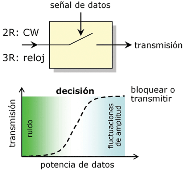
The two basic functional blocks of the regenerator are the clock recovery circuit and the decision element. These subsystems are usually semiconductor-based, although other technologies are also possible. The clock is a pulsed source that must be synchronized with the data pattern. In some cases, synchronization is performed electronically, using a gain-switching or mode-locked laser, or an electro-optical modulator. However, all-optical synchronization techniques are much more attractive. In this case, mode-locked lasers or self-pulsed DFB lasers can be used, both powered by direct current. The data sequence is synchronized if the data repetition rate and the clock frequency are similar and within the locking range. Since the regenerator's output signal will propagate through the optical fiber, the generated clock pulses must have a sufficient quality level (wavelength, side mode suppression, chirp) to allow for long-distance transmission. Regarding the nonlinear optical gate, it can be implemented using SOA-MZI interferometric structures (Conectrónica, no. 115, pp. 8-12) that achieve speeds of up to 100 Gbit/s. Other solutions are based on saturable absorbers. The typical transfer function of the optical gate is shown in Figure 2, where the two decision zones are clearly visible: a low level affected by noise and a high level affected by power fluctuations.
The main advantage of optical regenerators is that they eliminate O/E conversions and the use of RF electronic circuitry. However, 3R regenerators can never be completely transparent, as they must monitor the input signal according to its pre-determined bit rate and modulation format. Developing 3R optical regenerators that can operate at different bit rates is a challenge.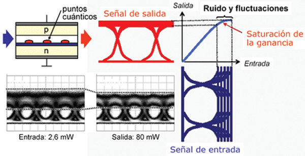 Additionally, IP optical networks based on asynchronous packet flow impose numerous limitations on clock recovery circuits, which must operate at ultra-fast speeds to respond in less time than a single packet. It goes without saying that electronic technology is even more constrained in these cases. Therefore, we can conclude that the clock recovery circuit is the most critical component of the optical regenerator.
In this and subsequent articles, we will analyze in detail various technologies, in addition to those previously mentioned, that enable the implementation of 3R optical regenerators. Most of these are still under investigation, although some companies have already announced satisfactory results, as well as some commercial products, which we will discuss below.
Developments by some companies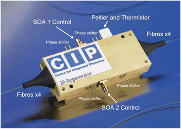 : Fujitsu announced a couple of years ago the development of a 2R optical regenerator for 40 Gbit/s signals. The device is based on a semiconductor optical amplifier (SOA) that uses quantum dots. Quantum dots are nanoparticles based on semiconductor crystals that can store electrons. SOAs can suppress noise and high-level signal fluctuations thanks to a characteristic known as gain saturation, whereby the optical gain (amplification rate) decays when a signal is very strong. However, SOAs have a rather slow gain saturation response (several nanoseconds), which rules them out for use as optical regenerators.
'
The technology developed by Fujitsu accelerates this response using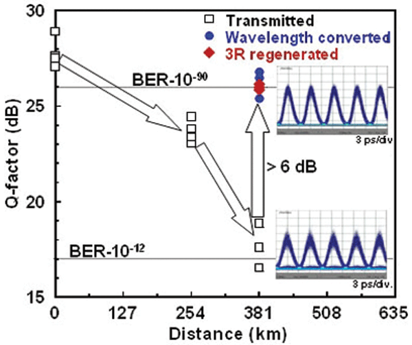 quantum dots. This allows for response times of just a few picoseconds. With a suitable design, a fast response, high gain, and high output power are simultaneously achieved at wavelengths near 1550 nm. The device's appearance, along with a graphical description of its operation, is shown in Figure 3.
Continuing with the specific case of 40 Gbit/s optical signal regenerators, special mention should be made of CIP (The Centre for Integrated Photonics). As discussed in a previous article, this company specializes in manufacturing SOA-based devices.
Their product catalog includes a 2R optical regenerator that employs an SOA-MZI. The device's appearance is shown in Figure 4.
Finally, we cannot conclude this article without highlighting a recent news item. On April 2nd, Oki announced the development of the first 3R optical regenerator capable of handling 160 Gbit/s signals, which has been tested in a real-world field trial. The performance results are shown in Figure 5, where a Q factor improvement of over 6 dB can be observed. The device implements an adaptive PMD compensator, and it has been demonstrated that a maximum spacing between regenerators of 380 km can be achieved. This distance is equivalent to transmitting a 160 Gbit/s signal between the cities of Tokyo and Osaka using a single 3R regenerator, thus validating the great potential of this technology.
Francisco Ramos Pascual. PhD in Telecommunications Engineering.
Full Professor at the Polytechnic University of Valencia.

