
 In the previous article in this series, we discussed the need to restore the quality of signals propagating through fiber optic links, presenting the basic principles of 3R regeneration. Now, we will delve deeper into some techniques and technologies that have experimentally demonstrated their suitability as key components of future 3R optical regenerators. Specifically, this article will examine clock recovery subsystems based on a Fabry-Pérot filter, a PLL, or a self-pulsating laser. These subsystems, in combination with SOA-MZIs, electroabsorption modulators, or semiconductor optical amplifiers, enable the construction of high-speed 3R regenerators.
Synchronous modulation and clock recovery based on a Fabry-Pérot filter.
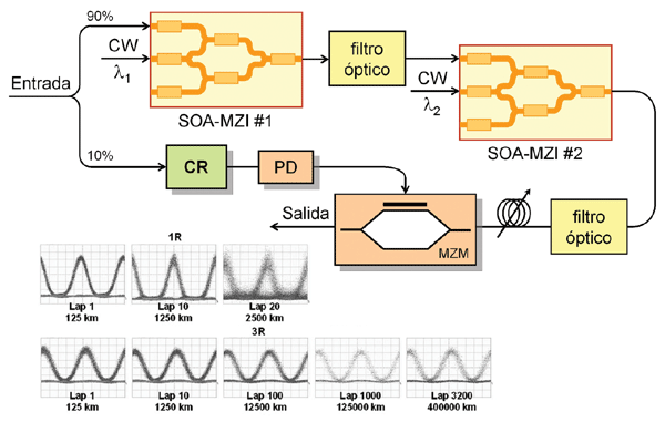
Synchronous modulation is based on using optoelectronic or purely optical techniques to remodulate the recovered clock signal. The system block diagram can be seen in Figure 1. Two cascaded active Mach-Zehnder interferometers (SOA-MZI) are used to shape the optical pulses that will subsequently be remodulated by the clock signal. In this case, electronic clock recovery is employed, as this signal must feed the RF input of an electro-optical Mach-Zehnder modulator. This, of course, limits the maximum bit rate at which the regenerator can operate. To demonstrate the feasibility of the technique, experiments were conducted on a recirculating optical link consisting of two LEAF fiber segments with a total length of 125 km (65 + 60 km) and compensating fibers. The 10 Gbit/s results in Figure 1 show excellent performance up to distances of 400,000 km (Z. Zhu et al, JLT, vol. 25, no. 2, pp. 504-510), especially when compared with measurements made without regeneration (1R, simply amplification).
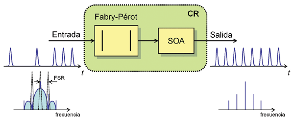 The key element of this regenerator is the clock recovery (CR) circuit. While an electrical signal is needed to power the Mach-Zehnder modulator, it is clearly desirable that clock recovery be performed using optical methods. For this purpose, the use of Fabry-Pérot filters has been proposed. These filters are characterized by a narrowband periodic response through which the clock frequency components can be extracted from the signal spectrum. This clock recovery subsystem consists of a Fabry-Pérot filter and a gain-saturated optical amplifier (SOA) (Figure 2). As a design requirement, the filter's free spectral range (FSR) must match the repetition rate of the data signal, as schematically represented in Figure 2. Attention must also be paid to potential frequency drift in the filter's response due to changes in the polarization of the input optical signal. By using temperature control of the device, amplitude variations due to polarization changes can reach up to 6 dB. Since the clock signal recovered by the Fabry-Pérot filter can exhibit amplitude variations dependent on the data pattern, especially when there are long sequences of zeros, a saturation SOA is used which reduces such variations by limiting the amplification.
Regeneration using Electroabsorption Modulators.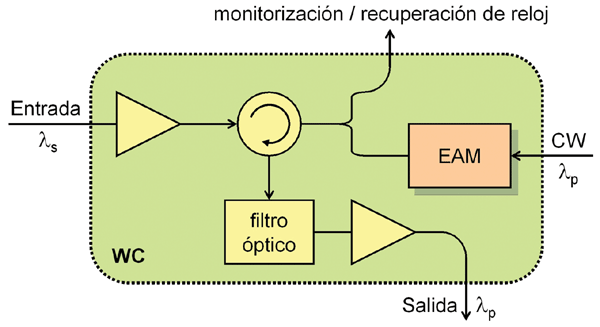 Wavelength converters based on the use of electroabsorption modulators (EAMs) can also be a good option for the design of optical regenerators. In this case, the advantage is a dependence on the polarization of the input signal of less than 1 dB, thanks to the characteristics of the EAM device. Since the regenerator architecture uses these wavelength converters, it is best to begin by describing their operation. The wavelength converter has two inputs for the data signal, ls, and the continuous wavelength, lp, as well as an output port for the converted signal, as shown in Figure 3. The input signal must have a sufficient power level to induce a cross-saturation effect of the absorption. In this way, the two signals propagating through the EAM interact, and the continuous wave is modulated by the input data circulating in counter-propagation. During high data levels, the EAM saturates, and the continuous wave passes through the device with minimal loss. Conversely, at low data levels, the device ceases to saturate, and the continuous wave experiences greater attenuation. Thus, the modulation of the continuous wave depends directly on the data signal pattern. Unlike the cross-gain modulation process in SOAs, in this case, the wavelength-converted signal is not inverted. The circulator is used to extract the wavelength-converted signal, while the optical filter eliminates any unwanted reflections in the EAM.
As shown in Figure 4, the optical regenerator employs two wavelength converters (WCs) like the one shown in Figure 3. The first converts the input signal, ls, to a different wavelength, lp, in order to duplicate the data. The second converter then restores the initial wavelength, ls. This cascaded configuration avoids crosstalk effects in the EAM, while ensuring that the signal is transmitted at exactly the same wavelength as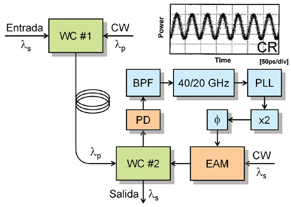 the original signal, which is also useful for preventing wavelength blocking at network nodes. The clock signal is recovered electronically using a broadband photodetector, a highly selective (high Q) filter, and a PLL circuit locked to half the clock frequency, in this case 20 GHz. Although optical recovery schemes are preferable, this type of circuitry still works correctly for bit rates of 40 Gbit/s (T. Otani et al., JLT, vol. 20, no. 2, pp. 195–200). To achieve 3R regeneration, the signal is resampled in the second wavelength converter using the recovered clock. To stabilize operation, the pulse width of the input signal can be increased using a high birefringence fiber, which facilitates synchronization between the input signal and the clock. As mentioned earlier, no complex polarization control system is needed, thanks to the low sensitivity of the EAMs.
Self-pulsating laser-based regeneration.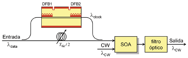 Self-pulsating lasers have been used in various experiments as clock recovery elements. As their name suggests, these are pulsed lasers whose cavity is designed to resonate at the desired repetition frequency, so that when the data signal is injected, it generates a pulse train (clock signal). Figure 5 shows a possible configuration implemented with two DFB sections and a central phase-control section. The device is called the PhasCOMB laser (C. Bornholdt et al., ECOC'01, Th.F.1.2). The two DFB sections are tuned to different wavelengths, generating two overlapping modes in the cavity, resulting in a beat at a frequency different from that of the two modes. For the device to function correctly, phase control in the central laser section is essential. This clock recovery scheme can operate at high speeds, having been demonstrated at 80 GHz and higher frequencies.
Its use in optical regeneration applications can be as simple as adding a self-powered amplifier (SOA) and a continuous-wave laser to the system. Figure 5 shows the block diagram of a possible 3R regenerator. The self-pulsing laser is used for clock recovery, and its output, along with the data signal and a continuous-wave signal, is applied to an SOA operating in nonlinear mode as a wavelength converter. Inside this amplifier, the data signal is transferred over the continuous-wavelength (CW) signal, eliminating the other signals by means of an optical filter. This is therefore a simple and cost-effective solution for the optical regeneration of high-speed signals.
In this article, we have analyzed different possibilities for the development of 3R optical regenerators. Examples of both optoelectronic technologies and photonic devices have been provided. All of them are characterized by their ability to operate at high speeds. In the next article, we will complete the analysis with several additional configurations.
Francisco Ramos Pascual. PhD in Telecommunications Engineering.
Full Professor at the Polytechnic University of Valencia.

