This can be done with the E-PRS using a real digital radar receiver, a waveform generator, and a programmable data and signal processor. This method, unlike the software simulation approach, adequately accounts for the response and limitations of a real hardware process, including nonlinearity, distortion, saturation, etc. This approach is commonly defined as a hardware-in-the-loop (HWIL) simulation system. Furthermore, this method allows for playback of the simulation and analysis of the collected data for in-depth analysis of collapse effectiveness or for training purposes.
 The E-PRS can simulate ground-based, airborne, and shipboard radars, as well as missile seekers (active and semi-active).
Targets and other emitters/scatterers can be generated at the RF level using a module called the Radar Environment Generator (E-REG) or third-party COTS components.
The E-REG receives the position and trajectory of the platforms from the external scenario simulator and generates the target material echoes accordingly.
The supervisory control of the entire system and the simulation, including scenario control, is managed by a computer with the appropriate software and physical interfaces that also provide the display and data analysis functionalities, as well as hosting the database of the user-programmed radar model.
 Multiple SUTs can be tested simultaneously with the appropriate E-PRS hardware and software configuration.
The E-PRS is also a valuable tool for radar systems engineering, for verifying radar effectiveness, and for testing new ECCM techniques.
Operating Principles:
The E-PRS TX pulse is generated by an arbitrary waveform generator; the waveform can be simple or complex to apply various pulse compression techniques (Chirp, Barker, etc.).
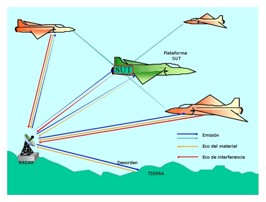
The System Under Test (SUT) receives the pulses generated by the E-PRS, weighted by the simulated antenna pattern. From this input, the jammer signal (SPJ or SOJ) is generated, which, along with the echo from the target material (from the E-REG), is injected into the RF or IF input (depending on the system architecture) of the E-PRS.
 Using the RX antenna simulator, the receiving antenna weighting is applied, and the signal is sent to the digital receiver for analog-to-digital and baseband conversion. The resulting signal is processed through a user-programmable matched filter that implements the appropriate filter according to the current TX waveform.
After filtering, the signal is sent to a series of DSPs that implement the desired radar signal and perform data processing according to a user-generated or pre-installed algorithm library.
The receiver reacts exactly like a real radar (of the selected type), providing the user with all the data necessary to evaluate the actual effects of the SUT on radar detection and tracking.
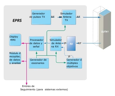
System Architecture:
The E-PRS, see block diagram, consists of the following functional blocks:
• Microwave receiver
• Digital receiver (4 or more channels)
• Microwave transmitter
• Programmable signal and data processors
• TX radar and RX antenna simulator
• RF/IF/Chaff/Clutter generator target(s). (E-REG or others)
• Environment Programming Software (Framework).
• Display and Data Collection / Systems Analysis.
The framework that runs on the E-ERP hosting computer has an open interface for adding user-defined radar model libraries. Once an element is added, it is reusable like the standard ones.
Software Features:
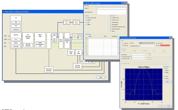
An advanced programming mode for creating radar models using a user-friendly, high-level graphical interface called the E-PRS Framework is available. With this tool, the user can generate a radar model according to their needs, simply by using the functional library included with the system.
The other way to program a radar model is to write the algorithms using the C/C++ language. In this way, the user can extend the basic E-PRS library and then simulate all possible radars.
Using the environment, beyond the platform and radar type, the operator can select all operational radar parameters such as:
• Adaptive filter: Barker, two-phase and four-phase, CHIRP.
• TX parameters (PRF, Pulse, Alternate, jitter, MOP, CW, etc.)
• MTI-AMTI-MTD processing
• Glint target
• SLB and SLC
• Doppler channel
• PDI/CFAR, TWS, TAS
• Loop tracking: Range, angle, speed.
• Ambiguity resolution
• Antenna type and radiation pattern.
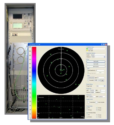
DCA (Information Gathering and Analysis)
This software tool, supplied with E-PRS, allows the user to collect all major events during the simulation and retrieve information in case of ECM success/failure generated by the SUT. The DCA records all macro events (i.e., tracking, loss of tracking, tracking errors, etc.) in addition to scenario and target information.
The entire simulation can be played back for training purposes using different display modes (PPI, A, B, C scope).