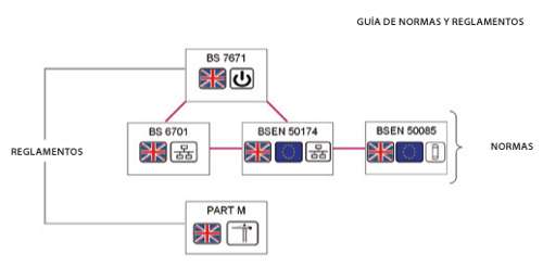
These aspects include a combination of regulations and standards. The former are the legal requirements that electrical systems must meet, which, obviously, can be deadly.
For this reason, containment and bonding are usually part of the electrical package, but how many structured cabling installers are familiar with the following standard, or even want to be? UK Cabling Regulation BS 7671
Safety
- Protection against
> Electric shocks
> Thermal effects
> Overvoltage
- Inspection and testing
- Requirements on special locations
. Currently, the 17th Edition of July 1, 2008.
The most important standard for cable installers is BS/EN 50174, which is divided into three main sections:
Part 1. Specification of IT cabling installation;
Part 2. Planning and practices INSIDE buildings; and
Part 3. Planning and practices OUTSIDE buildings.
Part 1 also addresses all aspects of containment quality and installation, stipulating that trunking systems MUST have smooth surfaces and be free from burrs, sharp edges, and other projections that could damage cables. Furthermore, trunking systems SHOULD provide all components with physical protection, and IT trunking SHOULD NOT be permitted in other supply systems, such as heating and ventilation ducts, etc.
Note: In the jargon of standards, the use of MUST indicates a prescriptive nature, while the use of SHOULD indicates a recommendation
In the last 12 to 18 months, much has been written about the move from Cat6 to Cat6A, with all articles focusing on performance, as well as related advantages and merits. One critical factor that is rarely discussed is its impact on containment. More time than ever before is spent inspecting and evaluating containment adequacy. With careful planning, this inspection aspect could be minimized, and costly, time-consuming errors in installation projects could be avoided.
However, a significant amount of training is needed before reaching this stage, at all levels, from installers and building services consultants to mechanical and electrical engineers, and even some containment manufacturers. The fundamentals have changed with Cat6A and are further complicated by the capacity requirements imposed by some containment manufacturers.
On top of all this, the situation is further complicated by the increasingly critical factor of power and data separation. Currently, the more susceptible the bandwidth is to interference, the more common the use of shielded cabling systems becomes.
Whether shielded or unshielded Cat6A solutions, both present separate, though not vastly different, problems stemming from their physical construction. The common factor is physical dimensions. The outside diameter (OD) has increased significantly—an astonishing 25–30%, in fact, from approximately 6 mm for Cat6 to around 8 mm for Cat6A. For example, where four 25 mm Kopex Cat6A cables could previously be run into a GOP box, it would now be difficult to fit three.
And the issue doesn't end there; the repercussions occur at all levels. The socket joint is one of the most sensitive areas. Many of these product designs were based on the electrical requirements of Cat6A, but without proper precautions, they can cause problems not only in capacity but, more importantly, in bend radii. A capacity requirement imposed by manufacturers has already reduced the number of Cat6A cables from 14 to just 3 due to the design of their bends, which yielded because of the angled parts that must be secured and the screw positions located inside the external compartments.
The next critical factor is the splice depth. Not only does it contribute to the overall capacity when splice-in with Cat6A, but great care must be taken with the bend radii. This increase in cable OD has natural repercussions. What was a 24 mm bend radius in Cat6 has suddenly become a 40 mm bend radius (MBR) with Cat6A. Such a bend radius can be achieved in the splice bends, but it is severely hampered by the depth of the back box. If you add a socket and an angled formwork module, which can add up to 200 mm, the problem becomes apparent. While the splice is 60 mm deep or more, with the exception of the MK Prestige 3D which is only 57 mm deep, its overall dimension has been designed to meet the needs of the data market and can accommodate even the thickest Cat6A cables, provided good installation practices are followed.
It may seem strange, but when sleeving cables in back boxes, sometimes less is more. By creating a loop inside the box (i.e., with the entry at the bottom), routing the loop upwards to terminate in a downward-angled connector makes repositioning the faceplate easier.
Attempting to bend a short length of thick cable can not only be difficult but also result in it being squashed into place with a yielded bend radius. Part 1 of BS/EN 50174 states that the design of termination points
MUST:
Allow safe access
; Ensure link performance (maintain minimum bend radii);
Leave sufficient clearance to install components according to the cable manufacturer's instructions.
The image below provides an example of how to do it WRONG!
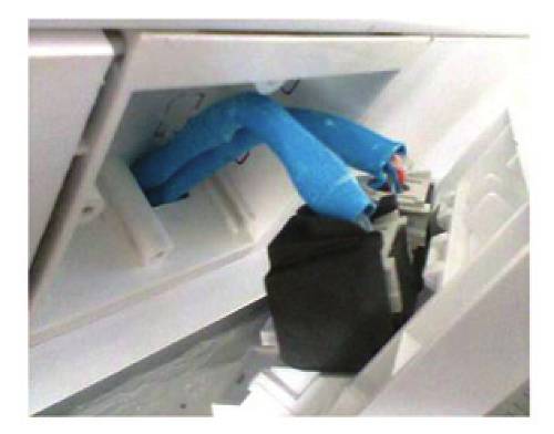
One socket-through cable management system manufacturer that has given these issues careful thought is Rehau. They consulted extensively with cable manufacturers and even members of standards bodies before finalizing their design. The result is their Profila Data product, one of the best on the market, with a total depth of 65 mm and a variable-depth back box featuring slots drilled at various angles to ensure that even the bulkiest cables fit without too much trouble.
While socket-through cable management is the area of greatest concern, not all the problems with perforated and basket trays have been solved. These problems are not limited to the upper outer diameter but also include the weight factor. In both shielded and unshielded cables, the conductor thickness has increased from 24 AWG to 23 AWG—a difference in gauge that, while it may not seem significant, adds up quickly. In the US standard for wire gauges,
the lower the gauge number, the thicker the cable, which is also related to the number of times the cable has been drawn.
While the latter factor has more to do with how the basket is secured or mounted than with the possibility of the volume of cable bundles crushing those on lower levels, it is still an aspect that must be considered.
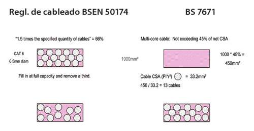
The increased outer diameter (OD) primarily affects capacity. A 300 mm² section of basket tray can comfortably hold 320 Cat6 cables with 20% capacity to spare. Using the same criteria, it would be difficult to fit 200 Cat6A cables. This is a critical consideration when planning main horizontal runs, as approximately 35% more basket tray will be needed for the same amount of cable.
The UK cabling regulations BS/EN50174 and BS7671 offer different calculations for determining capacity. For consistency purposes, cable installers should observe the BS/EN 50174 standard.
Wiring regulation BSEN 50174 BS 7671
Finally, two elements should be considered: Part M of BS7671 and BS/EN 50085 and the European junction standards; in BS/EN 50174-2, the latter are referenced as follows:
Clause 4.5 l
The junction should comply with EN50085-2-1
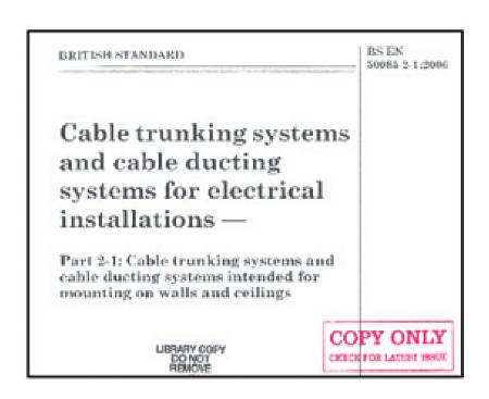
This is the safety and performance standard for the connection and covers:
- Fire hazard
- Access to moving parts
- Mechanical strength
- Heat resistance
Part M is probably the least used or applied building code and deals, among other things, with visibility requirements (BS 8300 – 2009). It stipulates that power outlets must be identified by visual contrast. This visual contrast is achieved by a 30-point difference in light reflectance values (LRV). LRV is the proportion of light reflected by a color. Essentially, pure white = 100 and jet black = 0.
Conclusions:
Containment used to be something "other people installed," which doesn't necessarily have to change. However, the cable installer should be informed about it early on to ensure the suitability of the installed components.