Finally, various tests conducted in independent laboratories are reviewed to verify the viability of UTP cabling in environments such as data centers where 10GBASE-T is already in use, and the need for higher-performance cabling for next-generation applications such as NGBASE-T (40Gbps).
Introduction:
Twisted-pair structured cabling systems are purely passive; therefore, on their own, they do not generate any type of electromagnetic signal. However, when connected to electronic equipment that forms a communications network for voice, data, and image transmission, they can become systems that radiate into the environment where they are installed.
Furthermore, the signals traveling through these cables can also be affected by electromagnetic radiation from other systems.
The arrival of very high-speed applications, such as 10GBASE-T, means that the transmission frequencies used are much higher than those considered until now. This may lead to some concern within the industry that, on the one hand, the cabling system poses a threat to other equipment or devices, and on the other hand, that to support these high speeds and frequencies, only shielded systems will be necessary. This paper will explain the feasibility of using unshielded systems for current applications, including 10GBASE-T, and will also address the need to begin using shielded systems to cope with the arrival of 40G applications.
Electromagnetic Compatibility (EMC):  In the US, the Federal Communications Commission (FCC) specifies radiation limits for network equipment and systems in two classes: Class A for operation in commercial environments and Class B for operation in residential environments. The limits for each class are specified in the following table
.
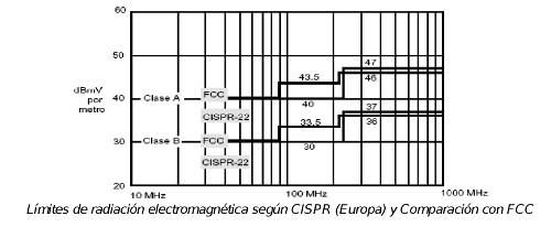 In Europe, the countries belonging to the European Union have adopted the IEC CISPR-22 standard (International Special Committee on Radio Interference), which also has Class A and Class B types and specifies a test procedure and emission limits that are very similar to the requirements set by FCC Part 15, Subpart B.
Thus, all products and systems marketed within the framework of the European Union must comply with the requirements of the Electromagnetic Compatibility Directive 89/336, which specifies two essential requirements:
- The device or system must not interfere with radio or telecommunications equipment
. - The device or system must be immune to electromagnetic disturbance due to sources such as radio frequency transmitters or other similar equipment. 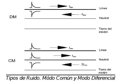 Types of Noise and Coupling
There are basically two types of noise on a cable:
• Common-Mode Noise (CM)
• Differential-Mode Noise (DM)
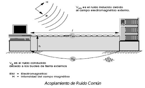 The following figure illustrates the two mechanisms of noise coupling to a receiver: induced noise due to an external electromagnetic field and conducted noise due to external ground loops. The common-mode coupling voltage (VCM) is a function of the electric field strength (E) and the loop area formed by a conductor of length (l) suspended at an average height (h) above the ground plane. Therefore, installing the cable close to the ground plane can have a significant effect on reducing the coupling of induced common-mode noise.
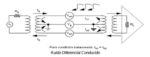 As for conducted noise (Vg), it is due to the potential difference of the grounding system between the work area and the telecommunications room, which will occur mainly in shielded systems (unshielded systems do not have metallic elements except for the pairs themselves). If the pair is balanced, the noise currents flowing in each conductor are equal in magnitude and flow in the same direction. It is known that equal currents flowing in each half of a primary winding produce opposite voltages in the secondary winding, canceling each other out at the receiver input.
Depending on the degree of imbalance in the wiring (usually due to installation problems), a portion of the common-mode noise signal is converted into a differential-mode signal that passes directly to the receiver. Longitudinal conversion transfer loss (LCTL), measured in dB, is a measure of the conversion of common-mode noise to differential-mode due to wiring imbalance.
Evolution of Applications and Twisted-Pair Cabling Systems
Just as the active device industry and data transmission applications in enterprise environments have evolved from low transmission rates (10BASE-T) to very high transmission rates (10GBASE-T and 40GBASE-T), an evolution of the cabling systems that support the various applications has also been necessary, requiring greater bandwidth and robustness against interference, internal and external noise, etc.
Each generation of Ethernet interfaces uses more efficient signaling protocols and improved signal processing systems, which mitigate or compensate for the intrinsic characteristics of twisted-pair cabling systems as the transmission frequency increases, such as NEXT or Return Loss (RL).
Twisted-pair cabling systems have also greatly improved their technical characteristics, especially bandwidth. While 10BASE-T applications could operate over Category 3 cabling using only two pairs, 100BASE-TX (Fast Ethernet) requires a Category 5 system, also using only two pairs. 1000BASE-T (Gigabit Ethernet) needs to use all four available pairs, in Category 5E, although Category 6 is highly recommended due to the limited NEXT margin offered by Cat5E in relation to bandwidth requirements, particularly the NEXT required by Gigabit Ethernet. Gigabit Ethernet uses bidirectional signaling or full-duplex transmission, which means that interfaces need echo cancellers (NEXT) at both ends.
The arrival of 10GBASE-T necessitates the use of a new Cat6A twisted-pair cabling system, with a bandwidth of 500 MHz and maximum lengths of 100 m.
10GBASE-T has a data transmission rate, or Symbol Rate, of 800 Mega-Symbols per second (MSPS), which, compared to Gigabit Ethernet's 125 MSPS, represents a 6.4-fold increase in transmission rate. The number of bits per symbol has also increased, from 2 bits in Gigabit Ethernet to 3.25 bits in 10GBASE-T.
In terms of maximum transmission frequencies, Gigabit Ethernet uses frequencies around 80 MHz, while 10GBASE-T requires frequencies above 400 MHz. This significant increase in transmission frequencies means that 10GBASE-T applications are much more vulnerable to electromagnetic interference (EMI), and therefore the cabling system supporting these applications must be very robust against EMC and EMI. 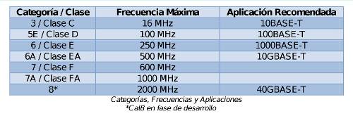 The following table lists Ethernet applications using twisted-pair cabling and the recommended category for each implementation.
Although the noise or disturbances present in the installation environment and the internal interference generated in each twisted-pair cable are very similar for 1000BASE-T and 10GBASE-T, noise elimination is much more difficult in 10GBASE-T applications than in Gigabit Ethernet due to the higher transmission frequency used. Therefore, 10GBASE-T interfaces need to cancel the following noise:
- Echo: The signal transmitted by the transmitter and received or reflected at the same point.
- NEXT: Interference between pairs on the same cable at the transmitting end.
- FEXT: Interference between pairs on the same cable at the receiving end.
- ANEXT: Interference from adjacent cables.  The following figure shows all these noises or interferences produced on the transmission channel using 10GBASE-T or any other full-duplex application.
Of all these disturbances, the most important and critical is alien crosstalk, or interference produced by adjacent cables sharing the same conduit. This is because other noise can be canceled by interfaces using processing techniques, but Alien Crosstalk cannot be eliminated due to its low correlation.
Therefore, it is necessary to use Cat6A twisted-pair cabling systems that mitigate or reduce this interference as much as possible. This noise can be reduced or eliminated either through tighter twisting, by increasing the cable diameter so that the interference is less pronounced over distance, or by shielding the cables. 10GBASE-T, also known as IEEE 802.3an, also has an Alien Crosstalk mitigation technique called Power Back Off (PBO). PBO is a technique that, if the link is short and therefore the attenuation it offers is not very high, reduces the transmission power level.
![]() Electromagnetic Interference (EMI) -
Electromagnetic Interference (EMI) -
The increased Symbol Rate in 10GBASE-T applications, and consequently the higher transmission frequency used, up to around 400 MHz, makes this application highly susceptible to external noise sources. The following figure shows various noise sources that can cause problems in 10GBASE-T transmission, as well as others that are much less detrimental, known as out-of-band noise.
Out-of-band signals can produce interference caused by their harmonics, although this is generally not a significant problem. Furthermore, the use of filters by transmitting devices, necessary to comply with EMC regulations, further reduces the problem outside the natural transmission frequencies.
Devices whose transmission frequencies coincide with those used in 10GBASE-T, that is, devices with transmission frequencies below 500 MHz, are the main culprits to consider. The signals radiated by these devices can couple into twisted-pair cables as common-mode (CM) signals. Furthermore, part of this signal will become Conducted Differential Noise, which, due to its lack of correlation, cannot be eliminated by the interface DSPs, causing errors in the transmission and decoding of the transmitted symbols.
10GBASE-T, Cat6A UTP Cabling and its Behavior with Regard to EMI.
Considering the increasing use of 10GBASE-T interfaces and the existing installed base of Cat6A UTP, SYSTIMAX and the independent laboratory NTS (National Technical System), accredited to perform EMC/EMI measurements according to IEC 17025 standards, have conducted a study of the electromagnetic compatibility and behavior of the GigaSPEED X10D unshielded twisted-pair cabling system and different types and generations of 10GBASE-T cards. 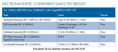 Five EMC tests were performed for Radiated Emissions, Electrostatic Discharge (ESD) Immunity, Radiated Immunity, Fast Transition Noise (EFT) Immunity, and Conducted Immunity. All tests yielded positive results, as shown in the table.
Additionally, various transmission and electromagnetic interference scenarios were constructed and tested to observe the performance of the 10GBASE-T application over GigaSPEED X10D UTP cabling, specifically regarding BER, packet loss, and link loss.
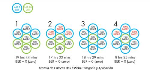 TEST 1: Mixing Cat6 and Cat6A cables transmitting at 1000BASE-T and 10GBASE-T.
Multiple combinations of cables of different categories exist for applications of varying types and speeds. However, perhaps the most problematic is mixing Cat6 and Cat6A UTP cables while operating at 1000BASE-T and/or 10GBASE-T. A 6:1 configuration was used, meaning one victim cable surrounded by six interfering cables. The objective is to verify the bit error rate (BER) on the victim cable. According to IEEE 802.3an, the BER in 10GBASE-T should be less than 10⁻¹² over a considerable period of time.
Figure 1 shows the tested scenarios, achieving a BER of zero in each case.
Based on the BER results, no problems are expected when mixing GigaSPEED X10D links operating at 10GBASE-T with other cables of different categories running at 1000BASE-T or 10GBASE-T. 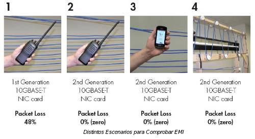 TEST 2: Verification of 10GBASE-T Packet Loss over GigaSpeed X10D cabling in a real interference environment.
Two generations of 10GBASE-T interfaces were used for this test: a first generation, now completely obsolete, and a second generation, which is currently the most widely deployed. Walkie-talkies, mobile phones, and fluorescent lights were brought near the installed links to observe the packet loss that could be caused by these interfering elements.
The first two tests were performed by bringing a walkie-talkie transmitting at a frequency of 147.5 MHz close to the cabling. This device was repeatedly activated and positioned 1 m away from the cabling. The result was that packet loss occurred on links using 1st generation cards, but there were no problems on links using 2nd generation cards.
To determine if 2nd generation cards could be affected by other interfering devices, the walkie-talkie was replaced with a mobile phone broadcasting at 900 MHz and a fluorescent tube screen, placed directly in the middle of the cabling. No packet loss occurred in either case when using 2nd generation cards.  TEST 3: Behavior in the Face of EFT.
The following test simulates the behavior of the cabling system and the application running on it when working alongside power cables containing fast transition noise (EFT). To do this, a power cable was glued onto a GigaSPEED X10D UTP cable and secured in a braided fashion so that it remained fully adhered along its entire length. An EFT burst with the following characteristics was injected onto the power cable:
- Voltage: 2kV
- Frequency: 5 kHz
- Period: 300 ms
- Duration: 15 ms
- Rise time: 5ns ± 30%
- Pulse width: 50ns ± 30%
- Source impedance: 50 Ohm ± 20%.
The response was again verified using a 1st generation and a 2nd generation interface. The test was designed to determine if there was link loss or failure due to EFT during the transmission of a 3.8MB file, repeating the test for at least 60 seconds several times consecutively. 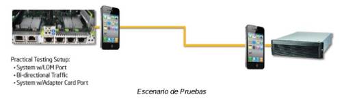 The result was that when the EFT burst was applied to the 1st generation interface, a link loss occurred and the interfaces reset. However, with the 2nd generation interfaces, there was no problem with this interference.
Recently, semiconductor manufacturer Intel conducted similar tests to verify the performance of next-generation 10GBASE-T X540 interfaces integrated into server motherboards (LOM) and operating over Cat6A UTP GigaSPEED X10D cabling. These new-generation interfaces incorporate a mechanism to reduce external interference induced in the cable, called a 5th Channel. 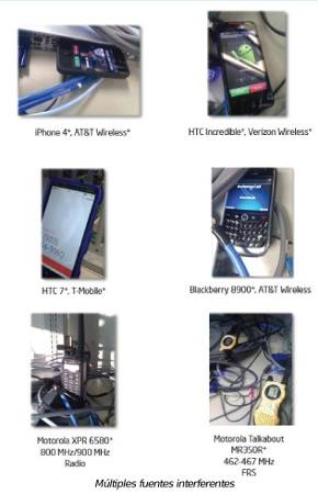 Multiple devices were used to induce interference, including iPhone 4 and HTC BlackBerry mobile phones, as well as Motorola XPR 6580 and MR350R walkie-talkies.
The results obtained using the various interference sources showed no link loss, the bit error rate (BER) was always below 10⁻¹², and packet loss was zero in any scenario.
'
'
Shielded Cabling and Shielding Effectiveness
When discussing shielded cabling, a crucial question arises: how effective is the cable shielding at reducing external noise? Answering this question is far from simple.
The shielding factor measures the effectiveness of shielding in the presence of an electromagnetic field and is defined as the ratio of the voltage induced at the receiver after the shield is introduced to the voltage induced at the same point before the shielding. 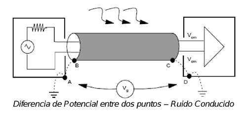 The shielding factor can vary with the operating frequency, type, thickness, and geometry of the shield, the method of connecting the shield, and other factors.
For safety reasons related to electrical shocks, the chassis of terminal equipment must be grounded, and the cable shield must also be grounded at both ends so that the shield protects the pairs from external electromagnetic fields. However, this also creates the possibility of conducted noise due to ground loop currents. 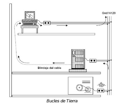 The following figure illustrates the ground loop currents caused by potential differences between the ground ends.
Conversely, if grounding is only at one end, the ground loop is broken, common-mode field coupling persists, and the shielding becomes ineffective at high frequencies (length > 1/10). Therefore, it is essential that shielded cabling systems be grounded at both ends; otherwise, the shielding will be ineffective at frequencies that are critical for the proper performance of 10GBASE-T.
Conclusions:
The emergence of new-generation 10GBASE-T cards and interfaces has led to increasingly greater immunity of 10GBASE-T applications to EMI.
A robust Cat6A UTP twisted-pair cabling system, such as the GigaSPEED X10D, guarantees the correct and flawless operation of 10GBASE-T, even in the most electromagnetically aggressive environments. Therefore, the ideal solution for developing new enterprise installation projects or data centers where 10GBASE-T applications are planned is a robust Cat6A UTP solution like the GigaSPEED X10D, as both implementation and maintenance costs will be lower than using other shielded Cat6A or higher solutions.
The arrival of new Ethernet applications with higher speed transmissions over twisted-pair cabling such as 40GBASE-T will force the use of shielded cabling, mainly because neither the cabling alone is capable of mitigating the various noises produced by transmission at these frequencies (1.6GHz or higher), nor do the interfaces have sufficient immunity and noise reduction and cancellation techniques to make it viable to implement a UTP system.
Therefore, technology dictates the need for specific cabling categories and shielding. And only now, and especially for 40GBASE-T applications designed solely for data center environments (the maximum distances this application allows over twisted-pair cabling will be around 30 meters, and in no case will it exceed 50 meters), is it necessary to have robust and properly installed shielded twisted-pair solutions.
Author: Alberto Martínez, Technical Manager, Spain&Portugal CommScope Enterprise