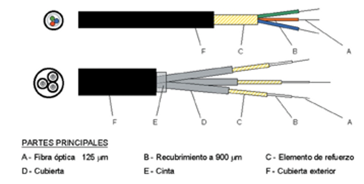
3.1 Construction
- LOOSE STRUCTURE (250 μm Optical Fiber)
· Unittube: houses one or more optical fibers in a single tube in a central arrangement:
- The optical fibers rest loosely inside each tube, which are usually hollow or lined with a water-resistant gel that prevents water from passing through.
- Optical fiber has an extra length to avoid tensile stresses when these are exerted on the cable.
- A layer of mechanical reinforcement (KEVLAR, Fiberglass, Polyester, etc.) is applied over the pipe as support during laying and installation operations.
- The outer covering or protection of the cable may be made of, among other materials, polyethylene, steel armor or shell, rubber or aramid fiber reinforcement, or a combination of different materials depending on its application (indoors and/or outdoors).
• Multitube: houses one or more optical fibers in different tubes forming concentric layers on a central support or reinforcing element:
- The optical fibers rest loosely inside each tube, which are usually hollow or lined with a water-resistant gel that prevents water from passing through.
- Optical fiber has an extra length to avoid tensile stresses when these are exerted on the cable.
- The tubes are usually colored to make them easier to identify.
- S/Z type pipe wiring/braiding arrangement.
- It contains a central reinforcing support (steel, KEVLAR, Fiberglass, etc.) on which the set of tubes with or without optical fiber are arranged concentrically.
- The outer covering or protection of the cable may be made of, among other materials, polyethylene, steel armor or shell, rubber or aramid reinforcement, or a combination of different materials depending on its application (interior and/or exterior).
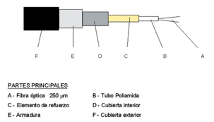
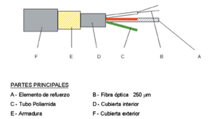
- ADJUSTED STRUCTURE
The tight structure of the optical fiber consists of a layer of plastic material 900 μm in diameter, deposited on the 250μm primary coating.
It provides additional protection to each individual fiber.
The same contractions and dilations occur in optical fiber as in cable.
It allows to be connected directly.
It provides greater flexibility and a smaller bending radius (cable assembly).
It is recommended for indoor installations.
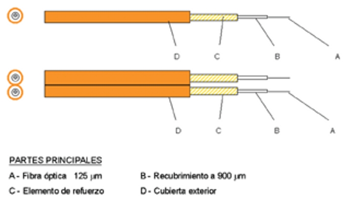
· Monofiber:
- A second coating at 900 μm is placed over the coating.
- Around it are arranged linear strands of aramid fiber in order to provide greater resistance to tensile and bending stresses.
- The outer cover (Ø 3mm) is made of flexible and resistant material (PVC, RUBBER, etc).
- Ideal for making patch cords (patch-cord, jumper) and pigtails.
· Bifiber (two optical fibers in parallel arrangement):
- A second coating at 900 μm is placed over the coating.
- Around it are arranged linear strands of aramid fiber in order to provide greater resistance to tensile and bending stresses.
- The outer cover is made of a flexible and resistant material (PVC, RUBBER, etc.) and arranged in a figure eight (parallel).
- Ideal for making patch cords (patch-cord, jumper).
- Recommended for indoor installations.
'
· Multifiber:
- A second coating at 900 μm is placed over the coating.
- Two or more optical fibers are distributed in a slight helical arrangement and aramid fiber strands are arranged linearly over the assembly in order to provide greater resistance to tensile and bending stresses.
- Each of the secondary coatings is identified by color.
- The outer cover is made of a flexible and resistant material (PVC, RUBBER, etc.).
- Ideal for vertical and horizontal cabling in buildings.
- A second coating at 900 μm is placed over the coating.
- Around it are arranged linear strands of aramid fiber in order to provide greater resistance to tensile and bending stresses.
- Each optical fiber is covered with a flexible and resistant material (PVC, RUBBER, etc.) (approximate diameter 2.8mm).
- A covering with the same characteristics is applied to the assembly of the small cables and aramid fiber as a reinforcing element.
- Ideal for direct connection of optoelectric equipment.
'
3.2 Cable selection
- The type of installation will be considered:
- Interior: vertical / horizontal.
- Exterior: underground piping; supported overhead; directly buried; etc.
- Enclosure elements and finish: cabinets, connection panels, distribution and splice boxes, wiring.
- Laying conditions:
- Mechanical aggressions: maximum tensile stress, impact resistance (shots).
- Thermal aggressions: temperature fluctuations, microcurvatures.
- Chemical attacks: hydrogen contamination (water-repellent protection).
- Installation conditions:
- Directly buried (structure):
- Metal support.
- Number of optical fibers.
- Loose-fitting protection with moisture-wicking gel padding.
- Wiring assembly with gel filling or similar.
- Cable protection and securing tapes.
- Thermoplastic cover.
- Reinforced steel armor or similar (High strength).
- Thermoplastic outer cover (Moisture resistant and fire retardant).
- Aerial installation (structure):
- Dielectric support.
- Number of optical fibers.
- Loose-fitting protection with moisture-wicking gel padding.
- Wiring assembly with gel filling or similar.
- Cable protection and securing tapes.
- Thermoplastic cover.
- Aramid braiding armor.
- Impact protection tapes.
- Thermoplastic outer shell
- SELF-SUPPORTING ELEMENTS (Anti-hunter protection).
- ATTACHED TO THE AT LINE
- Ducted Installation (structure):
- Dielectric support.
- Number of optical fibers.
- Loose-fitting protection with moisture-wicking gel padding.
- Wiring assembly with gel filling or similar.
- Cable protection and securing tapes.
- Thermoplastic cover.
- Aramid braiding armor.
- Thermoplastic outer shell.
- WITHOUT ADDITIONAL PROTECTION.
- EXTERNAL CABLES CAN BE DUCTED.
- RODENT PROTECTION ELEMENTS.
3.3 Manipulation
- Precautions during handling.
- Handling safety:
- Cutting and stripping the cable (using gloves and safety glasses).
- Pieces of optical fiber (deposited in containers, use of tweezers).
- Laser light (do not look into the end of an optical fiber. Plan for the laser connection).
- Cable tension (caution against mechanical traction, whiplash effect).
- Solvents and cleaning solutions (avoid prolonged exposure, risk of fire and poisoning).
- Fusion splicer (high risk of exposure to electrical spark).
- Handling with care:
- Respect curvature ratios:
- Variable depending on the EXT. Ø of the cable (e.g., 20 x Ø E).
- Different during installation (greater than after installation).
- Variable depending on the wavelength (greater at 1,550 nm than at 1,310 nm).
- Power line tension:
- Lower than that of conventional cables (generally specified by the manufacturer).
- Preferably hand-laid (whenever possible).
- Assisted laying (traction control: manual or automatic).
- Keep loads below specified levels.
Failure to respect the minimum bending radius, load conditions, or other recommendations may damage the cable and/or increase attenuation beyond the specified values.