- Make sure to take safety precautions (electrical disconnection, etc.).
- Install the grounding device (correct grounding).
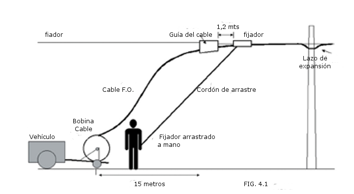
- Prepare equipment (see Fig. 4.1)
- Install guide cable and fastener to the latch.
- Respect the appropriate radii of curvature.
- Raise the fiber optic cable up to the guide cable and fixator.
- Maintain the safety distance of the cable reel (15 meters) in relation to the fastener.
- Install the fastener and secure it to the fastener (fixing clamp).
- Temporarily tie the cable to the latch on the clamp.
- Adjust the fastener for proper operation.
- Attach a tow rope to the fixer.
- Start the manual stretching operation smoothly and maintain the stretching speed while respecting the safety distance from the coil.
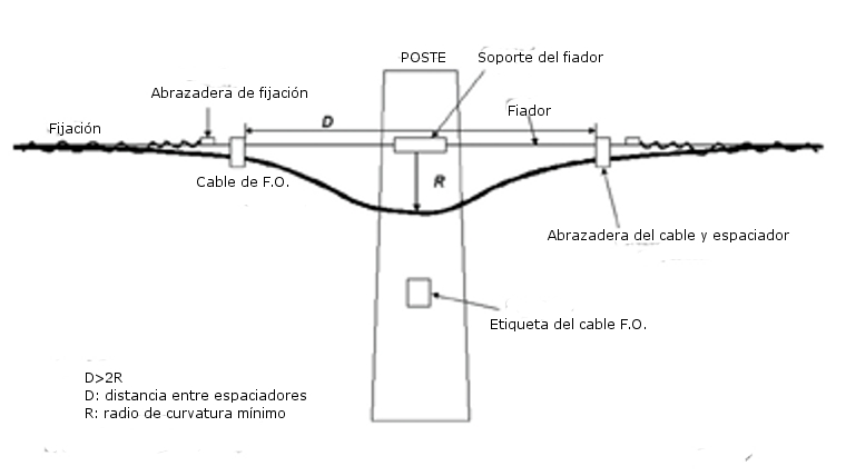
- At each pole the cable laying is stopped and the expansion loop is made (see Fig. 4.2) if necessary (not necessary in self-supporting cables).
- Continue laying the cable, identifying each pole with optical cable warning labels.
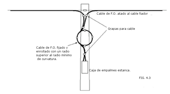
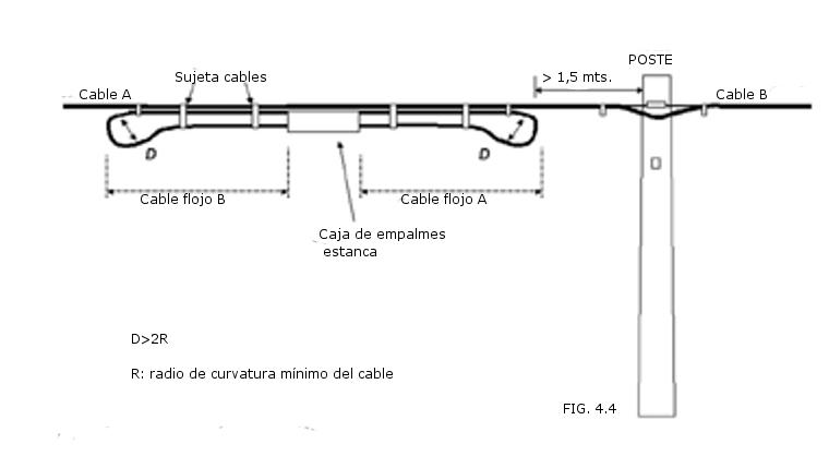
- When necessary, the junction boxes can be mounted on poles (see Fig. 4.3) or on the guy wire (see Fig. 4.4).
'
4.2 Ducted Installation
- Make sure to take safety precautions (identification of manholes, presence of gases, fuels, power cables, etc.).
- Preparation, inspection and identification of the ducts to be used (lubrication, sizing, etc.).
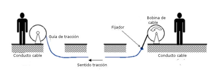
- Prepare traction guide cable, if necessary (see FIG 4.5)
- Install guide cable.
- Respect the appropriate radii of curvature.
- Place the cable reel on the appropriate supports to facilitate unwinding.
- Place the necessary pulleys and rollers to facilitate the pulling of the cable through the conduits and manholes of the route.
- Install the fastener and secure the latch (fixing clamp).
- Temporarily tie the cable to the latch on the clamp.
- Adjust the fastener for proper operation.
- Start the manual stretching operation smoothly and maintain the stretching speed, lubricating the cable if necessary.
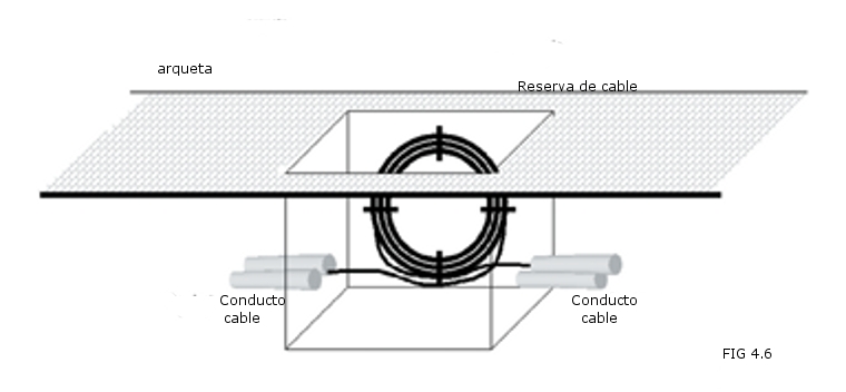
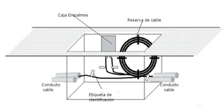
- In each manhole, the cable guidance will be checked and cable will be reserved (see FIG 4.6) if necessary (especially in manholes where direction changes).
- Continue laying the cables, ensuring that the ends of each section meet at a junction box for subsequent splicing. Allow sufficient length for making splices outside the junction box.
- Identify the ends of each cable in the splice boxes with optical cable identification labels (see FIG 4.7).
- Ensure that during laying (whenever possible by manual traction) a slack of 3 or 4 meters is maintained for unwinding to avoid excessive pulling force and chafing of the cable.
- Once the route is completed, the optical cable laying must be checked using an OTDR to ensure that the cable has not suffered any damage (breaks, excessive bend radii, etc.).
- Condition the cable and close each of the manholes along the corresponding route (cable stapling, identification of reserves, sealing of conduits, etc.).
'