Fiber optic cable should be checked in three stages:
Stage 1: Receiving the supply.
- Locating manufacturing defects.
- Location of defects caused by transport.
Stage 2: Making the connection.
- Locating installation defects.
- Locating defects in the assembly of connectors in the field.
- Locating defects in the fiber optic splicing process.
Stage 3: Acceptance trial.
- Network certification.
- Compliance with service specifications.
8.1 Visual Inspection
 - Microscopes (inspection of wiring in the field and workshop). Procedure:
- Clean the surface to be inspected.
- Select the adapter type on the microscope.
- Adjust the focus.
- Check status.
'
 - Fiber identifier.
- Identify the arrangement of the optical fiber.
- Locating splices in boxes.
- Location of fiber optic breaks in cords and cables.
- Optical continuity tester.
'
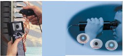
8.2 Optical power measurement
- Adapters for bare fiber (fiber optic cable connection).
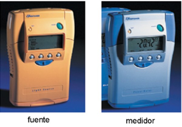
- Power meter (Appropriate wavelength selector).
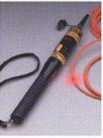
- Emission source (LED or laser suitable for the wavelength).
![]()
'
- Procedure
- Start-up of the equipment (for its stability).
- Select wavelength on both devices.
- Calibrate the equipment using patch cords and an adapter.
- Set to "0 dBr" or note the power value (dB) of the source.
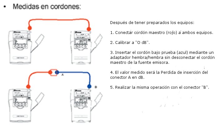
- Connect cord "A" to the adapter of the section to be checked.
- Connect cord "B" to the adapter of the section to be checked.
- Record the value obtained, repeat the procedure, or with the rest.
'
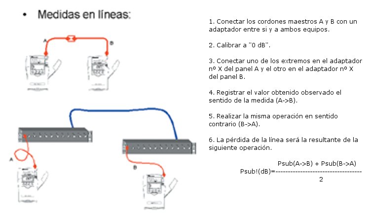
- Measurements in laces and measurements in lines.
'
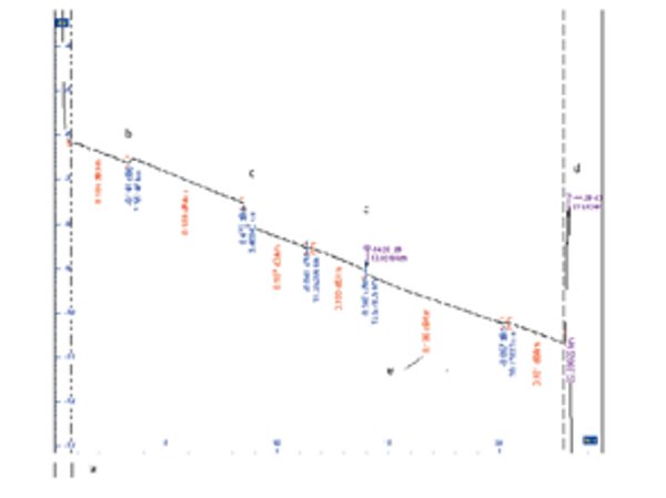
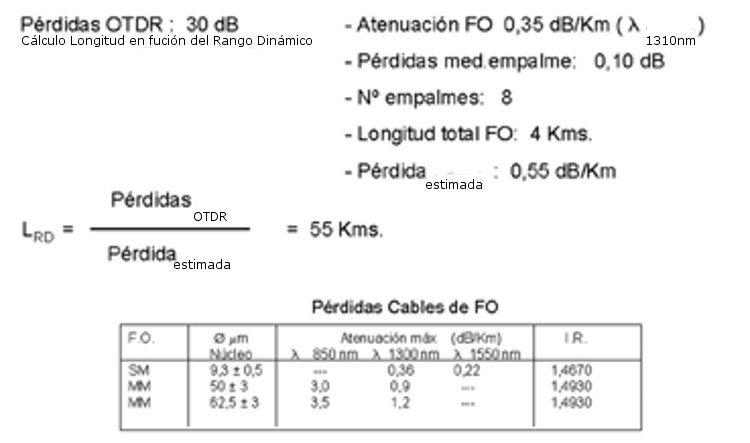
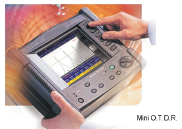
8.3 Backscatter Measurement (OTDR)
Optical reflectometer with time domain basis, sending short pulses of light to determine characteristics (length, losses, etc.).
- Suitable wavelength λ.
- Proper wiring.
- Sufficient dynamic range (depending on wavelength).
- Use of the dead zone eliminator (launch fiber).
 - PROCEDURE
- Equipment startup (for its stability).
- Select wavelength λ.
- Checking the dynamic range for the total measurement of events.
- Connect the launch fiber to the equipment (200-500 meters for MM / 1000 meters for SM).
- Perform first sweep to determine launch fiber.
- Enter identification parameters and measurements (λ, IR (refractive index), length, origin, end, etc.).
- Perform the first measurement on an optical fiber of the cable or section to be measured.
- Using the first one as a reference, perform the rest of the measurements.
- Analyze events and determine the end of the segment.
- Perform the same operation in the opposite direction.
- EVENTS
a) Dead zone.
b) Reflection (Fresnel):
- Change in refractive index (connections, mechanical splices, etc.).
- No reflection appears in APC type connections.
- Erroneous gain.
c) Splice losses:
- Fiber splice.
- Defective radius of curvature.
d) Final fiber reflection:
- Optical length.
- Return losses (light returning to the emitter).
'