
 In 1996, Kaelus (formerly Summitek Instruments) introduced the production of PIM test equipment to enable RF equipment manufacturers to verify the PIM performance of their products. In 2005, Kaelus introduced a portable PIM test kit that gave network operators the ability to perform PIM testing in the field. These field tests have proven effective in identifying components damaged during shipping, as well as installation workmanship issues in RF infrastructure. As a result, field PIM testing has been increasingly adopted by wireless system operators worldwide as a fundamental test for certifying optimal system performance.
PIM testing differs from traditional VSWR testing in that mechanical stress (intervention or bending) must be applied during the test to ensure its validity. If the PIM spikes above a threshold value during dynamic testing, the component or loose connection must be repaired or replaced. In most cases, determining the location of the PIM fault is relatively straightforward; the fault is located where you are intervening.
Occasionally, PIM faults will occur that do not produce large magnitude spikes when tested dynamically. Determining the location of these "non-responsive" or "static" PIM sources becomes more difficult and can often be time-consuming.
To address this problem, Kaelus has developed Range-to-Fault (RTF) technology, similar to that used in VSWR testing, to help identify the location of these static PIM sources. This article discusses the capabilities and limitations of this new technology, as well as a recommended testing method for implementing RTF analysis in the field.
 Existing PIM Test Equipment/Test Process:
The passive intermodulation test equipment transmits two 20W (+43dBm) test signals into the line or device under test. If the test signals encounter a nonlinear crossover, mixing occurs, generating PIM frequencies. The PIM test equipment measures the magnitude of the PIM generated by the test signals and displays this information to the test operator.
The 3rd order product (IM3) is used to characterize PIM performance both in the factory and in the field. The IM3 signal generated by a nonlinear crossover is generally of higher magnitude than other PIM products, allowing for greater measurement accuracy. Higher order products (IM5, IM7, IM9, etc.) typically decrease in magnitude by 5 to 10 dB for each successive PIM product. If the system's IM3 is controlled at a specified level, the higher order products (which are more likely to fall within the operators' own Rx band) will remain well below the specified IM3 level.
The specific test frequencies used to excite PIM defects in the cellular area are not critical, provided the following criteria are met:
- All RF components in the path (cables, antennas, TMA, etc.) must be able to pass both test frequencies and the IM3 frequency being measured.
- The two test frequencies must be within the operator's licensed spectrum or be shield band frequencies between licensed spectrum blocks to avoid interference with other operators. This applies to all system-level tests where the test frequencies will be transmitted through the antenna.
- The two test frequencies must be selected to produce IM3 within the receive band for that system. This will generally require test tones with wider frequency spacing than can be achieved within the licensed frequency block for a given market. For this reason, at least one shield band frequency must be selected.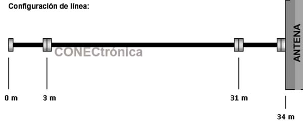
 During PIM testing, all RF components and connections in the line must be subjected to dynamic testing conditions. If an RF component or connection generates unacceptable levels of PIM under light mechanical stress, it must be repaired. Passing a dynamic PIM test ensures that the RF infrastructure is robust and will function correctly when exposed to normal environmental stress caused by wind and extreme temperatures.
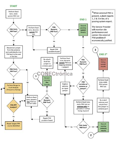
When testing a cellular area, it is recommended to perform a preliminary static PIM test to assess the system's initial condition. If the system passes the static test, the operator will proceed directly to the dynamic test. If the system fails the static test, the operator should disconnect the antenna feed line and install a low PIM load at the end of the line. This method allows test personnel to isolate the feed line to troubleshoot PIM issues independently of the antenna and objects irradiated by the antenna. Once the feed line passes the dynamic test, it can be reconnected to the antenna to verify system operation.
In some locations, especially rooftop installations, the PIM source may be located farther from the antenna. Since it is generally not the responsibility of installation personnel to resolve external PIM sources, operators will typically accept the following three pieces of information as evidence that the site was built to specification, even if the system PIM test fails:
1) Passing the dynamic feed line test (at low PIM load).
2) Passing the antenna test (antenna pointing skyward).
3) Failing the system test when both passing the antenna test and passing the feed line test are combined.
 New RTF analysis/technical limitations
Kaelus Range to Failure (RTF) technology is an analysis tool developed to enhance, not replace, standard PIM fixed pitch testing.
The RTF solution includes the additional hardware and software necessary to transform frequency information into time-domain plots using inverse Fast Fourier Transform (FFT) and digital enhancement algorithms. RTF technology is similar to the familiar Distance to Fault (DTF) function widely used in cellular areas to identify VSWR fault locations.
The RTF works by transmitting two 20W (+43 dBm) test frequencies into the system under test. One test frequency is fixed, while the second frequency is swept across a range to produce IM products in the receive band of the system under test. Because RTF analysis requires high-power signals to be swept out of the operator-licensed spectrum, this test should only be performed on systems terminating at a low PIM load to avoid interference.
The inverse FFT algorithm is used to reconstruct pulses across the time-domain range by digitally summing the quantized phase and amplitude components of each affected frequency in the computation. The more bandwidth available for analysis, the sharper the edges of the mathematical pulse, providing improved resolution of more closely spaced PIM sources.
If resolution is defined as the distance between two pulses of equal amplitude, separated by a 6dB null pulse, the resolution in meters that can be achieved through this analysis is expressed by the following equation:
Dd = 150 vf / BW
Where: Dd = resolution in meters; vf = velocity factor (% of the speed of light);
BW = PIM sweep bandwidth in MHz. 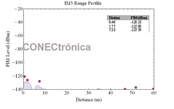
Using the PCS spectrum as an example (Tx = 1930–1990 MHz and Rx = 1850–1910 MHz), the maximum IM3 sweep range achievable in the PCS Rx band using two PCS Tx tones is 40 MHz. This is accomplished by keeping one test frequency fixed at 1930 MHz and sweeping the other test frequency between 1950 and 1990 MHz. This frequency combination will generate IM3 products from 1870 to 1910 MHz in the PCS Rx band. Using this 40 MHz of IM3 sweep bandwidth and a cable speed factor of 0.88, the maximum resolution achievable using only the PCS spectrum is 3.3 m. Kaelus has employed proprietary signal processing techniques to further improve resolution, but the absolute accuracy of the prediction algorithm will suffer when multiple PIM sources are within the minimum resolution distance on the line.
The most effective way to use RTF analysis is to systematically eliminate the
largest PIM source identified on the line. Repeat the analysis and continue eliminating the largest PIM source found until all significant static PIM sources have been removed. Regardless of its location on the line, the algorithm will be able to predict the distance to the largest PIM source more accurately. Each time a PIM source is repaired, the accuracy in locating the next largest PIM source will improve.
As mentioned initially, RTF analysis is not a substitute for dynamic PIM testing. RTF analysis will enhance site testing and potentially accelerate the elimination of static PIM sources in the cell area. However, the analysis alone should not be used to certify the quality of construction because:
- Knowing the range to a fault is a useful starting point but does not guarantee that there are no other hidden PIM sources within the RF power system.
The absolute value of the RTF PIM magnitude cannot be exact due to distortion caused by the frequency-sensitive group delay in RF devices such as overload accumulators, filters, TMAs, etc.
“Phantom” PIM sources can be created as a result of mathematical calculations and/or system impedance mismatches that reflect PIM generated at different locations on the line.
The process flow diagram shown in Figure 2 illustrates the correct way to use RTF analysis when performing PIM testing on a cell area. The cells highlighted in yellow represent the RTF test loop for removing static PIM sources.
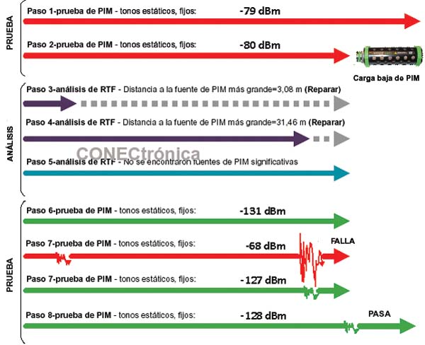
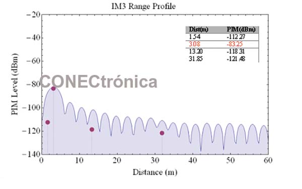
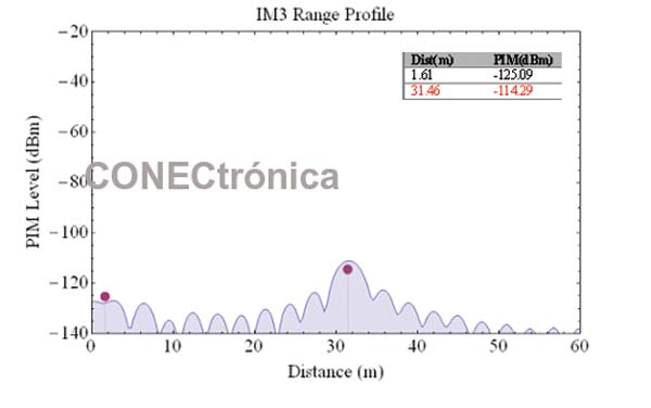
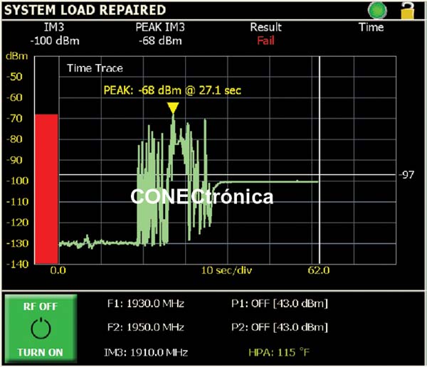
The data presented in Figure 3 shows the actual measurements recorded while following the flow diagram to repair a system with multiple static and dynamic PIM problems on the line.
Example Site Data:
The example in Figure 3 shows the results of an actual test on a feed line with multiple static and dynamic PIM issues. The results not only demonstrate the advantages of RTF technology but also confirm the importance of dynamic PIM testing in a cellular area.
Selected reports/screenshots
Figures 4, 5, 6 and 7 show the selected reports/screenshots corresponding to steps 3, 4, 5, 7.
Conclusion
As shown in the previous example, RTF analysis can accurately predict the location of multiple static PIM sources within the RF infrastructure. With this information and by following the indicated test procedure, PIM test personnel should be able to repair sites more quickly and reduce site-to-site repair time variability.
As also demonstrated in the previous example, RTF analysis does not replace the need to perform dynamic PIM testing on the RF power system. RTF analysis will be able to accurately predict the location of static PIM sources that you can see, but it will not identify PIM sources that are excited only by mechanical stress.
Finally, RTF analysis is a swept-frequency test and should only be performed on systems terminating at a low PIM load. Testing at a load will prevent the emission of high-power test frequencies outside the operator's licensed spectrum and eliminate the possibility of interference.
Author:
Tom Bell and John Nankivell, KAELUS.