In such cases, the device under test (placed on a substrate or wafer base) needs to be connected to the measuring instrument via some type of interface that provides a mechanical and electrical connection. This interface typically has a probe-based structure, known as a test fixture, and may consist of a connection to a fixed base (screwed or welded) or a "universal" solution that provides flexibility, efficiency, and measurement quality. There is also a large group of complex systems based on probe stations with their own application segment (some of which may overlap with the applications of test fixtures), although most of these tend to add complexity and higher costs.
The comprehensive characterization and high-quality measurements required by most test devices generally necessitate the use of a vector network analyzer, which provides measurement results in the form of S-parameter vector units for magnitude and phase. A complete measurement system typically includes a test fixture, a vector network analyzer, and a substrate calibration kit (for calibration on the fixture itself).
The term “universal” in the context of test accessories refers to their compatibility with a wide variety of device shapes and sizes, their broad frequency range, connection repeatability, added functionality such as polarization and multiport device testing capabilities, as well as their ease of use and excellent overall reliability and performance, including return loss and insertion loss of the accessory itself. For example, the accessory shown in Fig. 1 allows for repeatable and precise transitions from coaxial cable to microstrip or coaxial cable to coplanar waveguide (CPW), providing substrate measurement capabilities for component and device design.
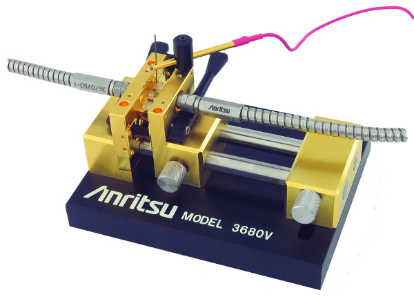
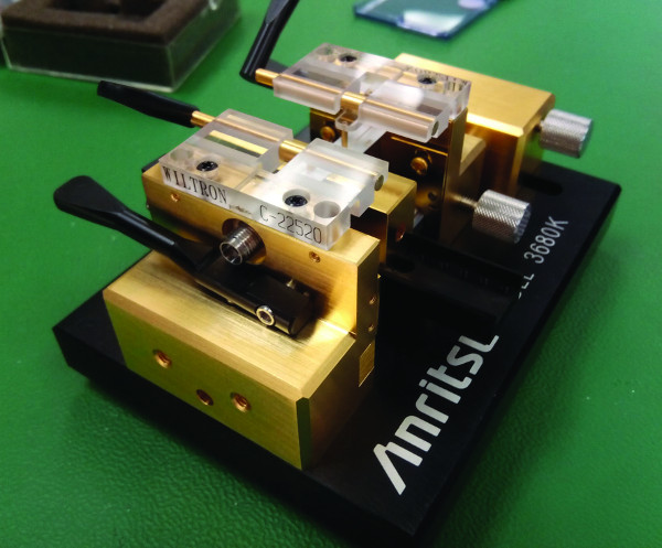 Figure 1. Universal test accessories.
An added advantage of this type of accessory is that it offers a certain level of on-site maintenance, thus increasing flexibility from the engineer's perspective. If, for example, the accessory is damaged due to an accident, its main parts can be replaced on-site, saving time and money, as the measurement process is not interrupted.
An ideal scenario for a test accessory with the corresponding interface between a device under test and a measuring instrument (vector network analyzer) would be a completely "transparent" connection, with no insertion loss and infinite return loss (no mismatch), a flat frequency response known as linear phase, and no leakage between ports (infinite isolation), which is certainly not feasible. Many factors influence the quality of measurements; as it is part of a measurement system, all its components (the vector network analyzer with its components, cables, adapters, and accessories) will introduce errors, thus increasing measurement uncertainty. Furthermore, the performance of the device under test also affects the overall measurement accuracy. However, it is possible to eliminate most of these measurement errors by using vector error correction techniques of the analyzer within the calibration process, which is based on well-defined high-quality calibration standards as reference items.
Random and Systematic Errors:
In most measurements performed by RF vector network and millimeter-wave analyzers, error terms are classified as either random or systematic.
Random errors are unpredictable and therefore cannot be corrected during the calibration process. The main factors that increase random errors are connector repeatability, cable stability, environmental changes (excluding drift effects), frequency repeatability, and noise. Good measurement practices are essential to reduce random errors.
Systematic errors, on the other hand, include factors such as directivity, source-load matching, isolation, and reflection and transmission tracking. Although they represent the most significant sources of measurement uncertainty, they can be greatly reduced during the calibration process (and subsequent error correction). Some residual effects remain uncorrected because calibration standards are not perfectly defined and the error models used to describe the measurement setup are not perfect. Residual errors can be used to calculate total measurement uncertainties and are specified within the technical specifications of the vector network analyzer for various calibration algorithms. This helps to determine the level of measurement accuracy available from an instrument under given conditions.
The main issue for a measurement system using a test fixture is that the aforementioned uncertainty terms are defined for the standard coaxial calibration kits of the vector network analyzer. This means that the error effects are only eliminated up to the coaxial connectors of the cables used in the test.
Various practices can be employed to eliminate the contribution of a test fixture from the measurement results of a device under test. These are all applicable to the corresponding use cases, depending primarily on the required measurement accuracy. The performance of the test fixture is also directly related to the performance of the device under test and determines the level of calibration required to meet the measurement uncertainty criteria.
De-embedding is a software tool in the vector network analyzer used to mathematically eliminate the effect of test fixtures from the measurement results. The test fixture (or "network" in this case) must be accurately measured beforehand using an S-parameter data file or a simulated model of the fixture. Calibration is performed using coaxial standards.
![]() Figure 2. De-embedding process (eliminating the effects of the fixture from the measurement of the device under test).
Figure 2. De-embedding process (eliminating the effects of the fixture from the measurement of the device under test).
The accuracy of measurements in general can be determined primarily based on the quality of the accessory's S-parameter data (measured or modeled), which is quite difficult to obtain in complex applications. If the actual performance of the test accessory does not match the modeled or measured data, errors occur. De-embedding is also difficult to apply to devices under test with low losses and does not account for mismatch error terms. In such cases, calibration within the accessory's CAN bus provides a more accurate representation of the device's S-parameters.
Accessory Calibration: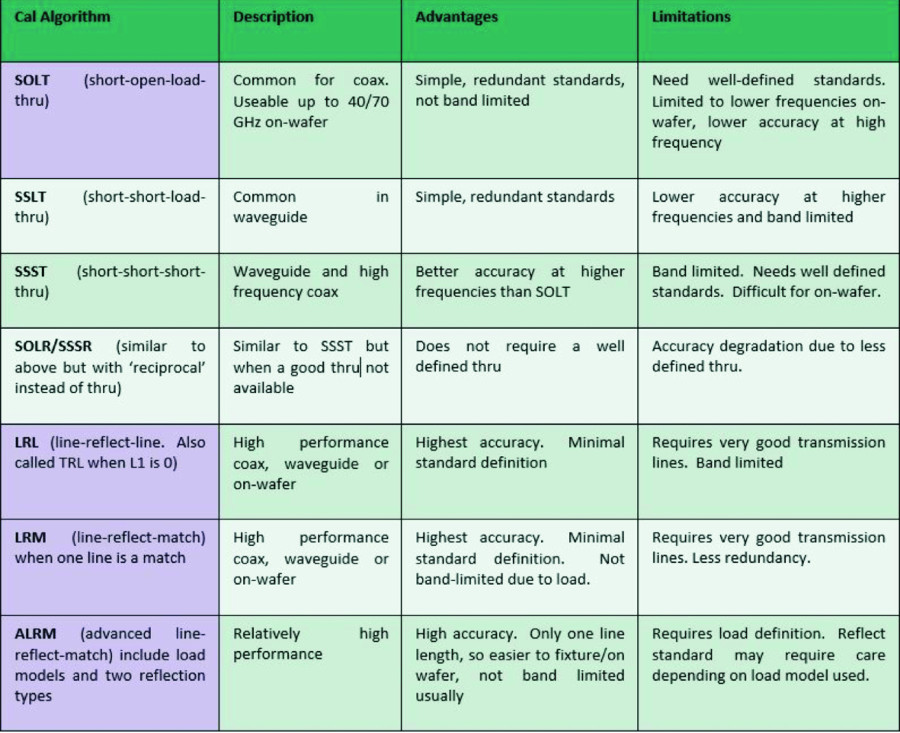
 There are two basic methods for calibration within a two-port accessory: OSL(T) (open-short-load (through)) and LRL/LRM (line-reflect-line/line-reflect-match). LRM calibration is a variation of LRL calibration, in which a load (termination) is used instead of the second line. There are also modifications such as ALRM (Advanced LRM), an Anritsu calibration technique implemented in the VectorStar calibration menus that uses different load models for each port and two reflection standards. Table 1 provides a list of typical available calibration algorithms and their appropriate applications "in the accessory."
The measurement accuracy will depend primarily on the calibration standards—the precision with which the standards have been defined—and the number of error terms that can be corrected will depend on the algorithm and type of calibration selected. For the two-port device to eliminate all 12 terms (the systematic errors mentioned above: directivity, source adaptation, reflection tracking, load adaptation, transmission tracking, and isolation in both directions (for signal flow), a total of 12 terms) will require a full two-port calibration and error correction. This will provide the highest measurement accuracy but requires more calibration standards.
LRL calibrations offer the best accuracy but have a limited bandwidth. OSL and LRM calibrations, while less accurate, cover a wider frequency range and can be calibrated at lower frequencies. LRM calibrations result in better source matching than OSL calibration. To improve broadband calibration, LRL and LRM calibrations can be combined. LRL/LRM calibration is also preferable in microstrip environments because the corresponding standards are easier to fabricate than for OSL. OSL standards also require accurate characterization of the quality measurements. Figure 4 shows some examples of OSL standards "in the accessory.".
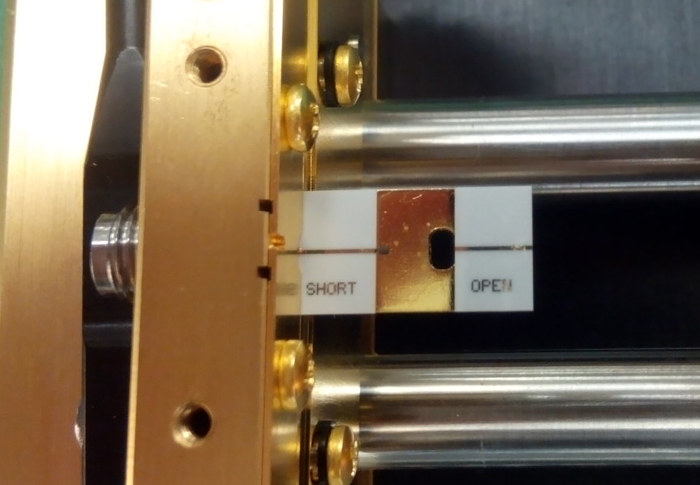
 Picture 4a – Open-Short Calibration Standard within the 3680 series UTF
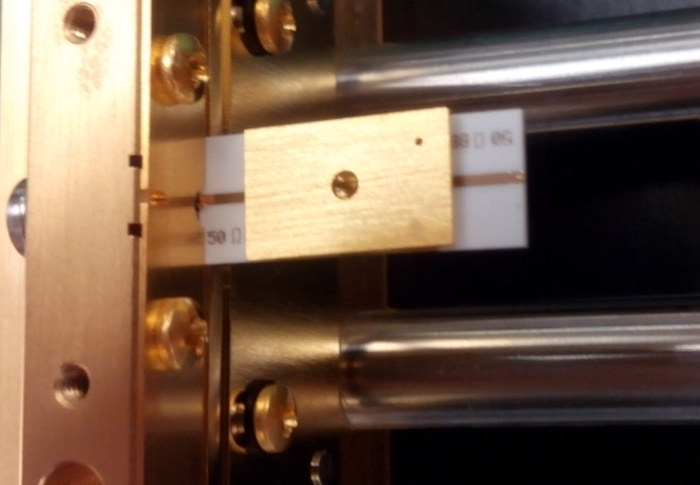
Picture 4b – Load Calibration Standard inside the 3680 series UTF
Figure 4. Calibration standards “in the accessory” for OSL calibration.
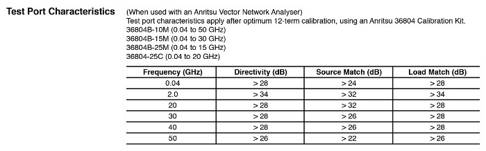
It is very useful that the "on-the-accessory" calibration setup also incorporates verification components to help the engineer qualify the measurement system. Furthermore, it is important to have specifications for the residual error terms that can be obtained using the system setup (comprising the vector network analyzer, the test accessory, and the "on-the-accessory" calibration kit). This gives the engineer confidence in the accuracy of the measurement and the results obtained. Table 2 shows an example of this valuable data.
The engineer can also use a dedicated "uncertainty calculator," such as Anritsu's "Exact Uncertainty," to gain even greater confidence in the level of accuracy. Incidentally, since the microstrip represents a dispersive medium in which the phase shift is not linear with respect to frequency, the vector network analyzer's ability to compensate for this dispersion can improve the accuracy of vector measurements.
Conclusion:
The challenge posed by the proliferation of new RF/millimeter-wave designs will require accurate and high-quality device characterization. Having the right tools and understanding the importance of proper calibration, along with the algorithms mentioned in the article, will ensure best practices and improve the quality of the component/device design.
Author: Maksim Pud, Anritsu EMEA