
The CAN-Bus Tester 2 verifies the bus configuration before powering on devices with its bus wiring test and performs physical layer measurements while the bus is operational. Thanks to the CAN-Bus Tester 2's protocol monitor, it's possible to analyze the data transmitted by the nodes, and its long-term monitoring will display scattered errors and progressive signal loss, aiding in rapid fault detection.
 The CAN-Bus Tester 2 is compatible with all CAN, CANopen, DeviceNet and SAE J1939 networks with special support, and standard support for Isobus, NMEA 2000 and SafetyBus P, Energy bus, CANaerospace, ARINC825, MilCAN and CANopen Lift.
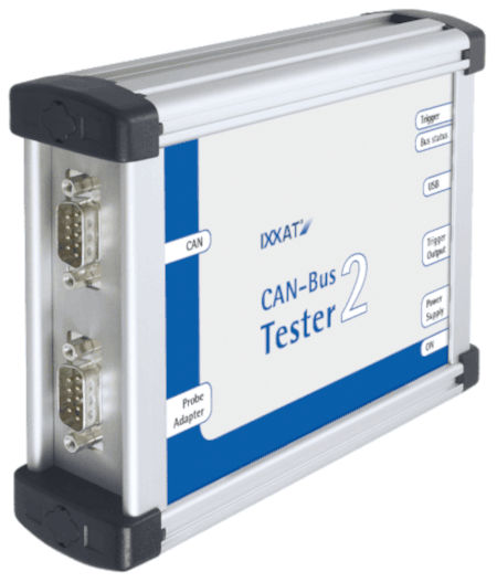
The CAN-Bus Tester 2 is essentially a 2-in-1 device.
One part is responsible for physical-level analysis. Sampling each individual bit 64 times enables a very detailed evaluation.
The other part is a CAN-to-USB interface for comprehensive protocol analysis. Both parts of the device can operate independently or simultaneously.
Among many other options, it's possible to automatically stop protocol analysis if the physical measurement device detects a problem. This allows data traffic to be evaluated immediately before an error occurs.
Bus Wiring Test
: This wiring test detects line short circuits, line breaks/cable breaks, correct CAN end-of-line termination/resistance, CAN bus power supply, and the total length of the CAN line/cable.
To ensure correct bus wiring, it is recommended to perform this wiring test at the beginning of any measurements during installation.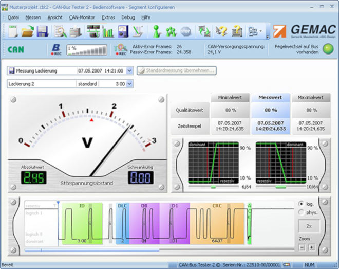
Measurements of a node
When connecting the CAN-Bus Tester 2 to the CAN bus line, a green LED should appear on the screen, confirming that there is data traffic.
First, you need to initiate the transmission speed scan, and then begin the node search. At this point, all messages on the bus are received and analyzed, and all nodes are listed with their IDs. For better visualization, you can edit the node names to facilitate identification.
The "view all stations" option provides an overview of signal quality levels, and the bar chart allows for easy comparison. Continuous mode displays minimum and maximum values, enabling simple comparison with previously saved measurements to identify any degradation trends in the installation.
The "station view" option displays the individual values of a node and also shows a decoded physical and logical oscillogram. With this option, it is possible to check the quality level, edge slope, and undisturbed voltage range. When a continuous measurement begins, the minimum and maximum quality levels and the variation of the undisturbed voltage range are also displayed.
Online Monitor:
This measurement runs continuously and is compared to set thresholds, recording an error when a threshold is exceeded. In single measurement mode, the measurement stops and a fault message is displayed on the oscilloscope screen, while in continuous mode, the error is marked on a timeline. This option is very useful for showing when a threshold was exceeded or if an error occurred.
The observed values are:
Active error frames / passive error
frames Overload frames
Recognized error
Overall quality level (0… 100%)
Undisturbed voltage range (minimum differential voltage without noise)
Free skew (worst up and down skew of a message)
In addition, for these logical and physical measurements, the CAN-Bus Tester 2 continuously determines the bus traffic load, the bus status, and optionally the CAN supply voltage.
Protocol Monitor
The CAN-Bus Tester 2 software integrates multiple optional functions of the CANvision protocol monitor, which are easily activated by purchasing a corresponding license.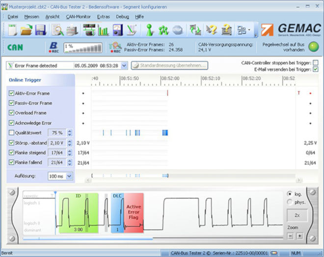
Licensing Model:
In its basic configuration, the CAN-Bus Tester 2 is enabled for the CAN-Bus system. All physical CAN-Bus measurements can be performed within this system.
Additional licenses are available for CANopen, DeviceNet, and SAE J1939 systems. These licenses greatly simplify the identification of messages to the actual nodes.
The optional protocol monitor is for logic bus analysis in CAN (transmit/receive), CANopen (receive), and SAE J1939 (receive) bus systems.
It is possible to receive the CAN-Bus Tester 2 software for free to perform measurements on the CAN-bus.


