 Any of these standards establishes maximum attenuation characteristics for cables, connections and splices, while also establishing maximum lengths that will depend primarily on whether it is horizontal or trunk cabling and whether the fiber used is multimode or single-mode.
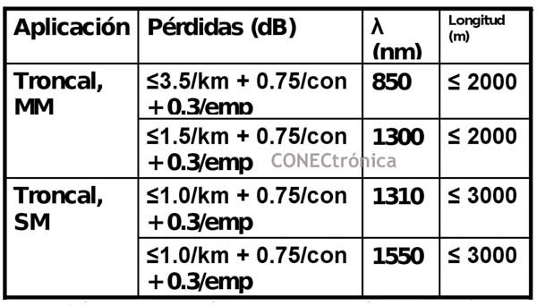
The following table shows the maximum attenuations allowed by these three regulations for cables, connections, and splices.
As can be seen, the regulations establish a maximum attenuation for fiber optic cable, which, depending on the fiber type and the operating window, will be 1dB, 1.5dB, or 3.5dB/km. They also establish a maximum attenuation for each connection, defining a connection as the joint between two connectors and a coupler or adapter that aligns them. Regardless of the connector type and whether it is multimode or single-mode, the maximum permissible attenuation is 0.75dB. Finally, the maximum attenuation for splices, regardless of whether they are mechanical or fusion splices, multimode or single-mode, is 0.3dB.
It's worth noting that the attenuation values established by current regulations are excessively high and permissive, both considering the possibility of achieving much better values with existing components and the maximum attenuation allowed by the most demanding applications, such as 1000BASE-SX (3.56dB), 10GBASE-SR (2.6dB), 40GBASE-SR4, or 100GBASE-SR10 (1.5dB). Therefore, it's advisable to consult the recommendations of the fiber optic cabling manufacturers to determine the maximum permissible attenuation for the links.
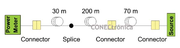
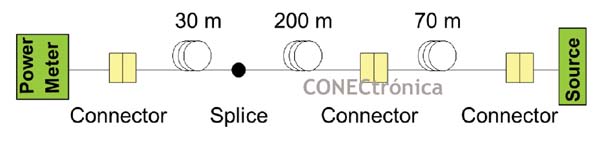
Knowing these values, we can perform an exercise to determine the maximum attenuation of a link.
The maximum attenuation of this link must be 3.60 dB, so compliance with the regulations will imply an attenuation value for said link lower than this value.
 In late 2006, ISO/IEC TR 14763-3 and ANSI/TIA/EIA TSB140 were approved, defining new technical specifications for the measurement components used in the testing or certification of fiber optic links. These new values are 0.1 dB between multimode reference connectors and 0.2
 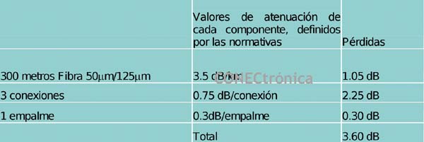 dB between single-mode reference connectors. When comparing a reference connector with any other type of connector, whether standard or non-standard, this maximum attenuation will be 0.3 dB for multimode and 0.5 dB for single-mode.
The reference connectors or connections are those used to perform the measurements; that is, the patch cord connectors that will be used, along with the measuring equipment, to carry out the necessary certifications.
Likewise, these technical reports (TRs) define two measurement levels:
- Level 1: OLTS (Optical Loss Test Set)
- Level 2: OTDR (Optical Time Domain Reflectometer).
Therefore, if either of these two standards is used to certify optical fiber, the maximum permissible values for the link will differ from those expressed in the table above, in accordance with ISO/IEC 11801, and will be as follows:
It can be seen how the maximum allowed attenuation value for this link has been reduced from 3.6 dB to 2.7 dB, that is, by 0.9 dB.
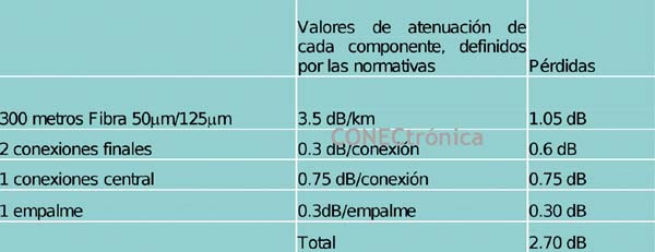
Therefore, the ISO/IEC 14763-3 standard is much more restrictive than any other standard and is recommended for use when carrying out Level I certifications.
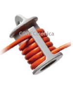
It is worth mentioning the use of mandrels for multimode link certification.
Mandrels are cylinders used to wind several turns of the light source's output patch cable. The number of turns depends on the patch cable type and should be determined by consulting the measuring equipment manufacturer. These mandrels act as a filter. This filter eliminates higher-order modes, which are the most susceptible to cable bends and can be lost with the various bends in the cables and patch cables, thus altering the light level reaching the opposite end. Therefore, to prevent measurements from varying during the certification process simply due to changing the patch cable's position, regulations require the use of these mandrels, which eliminate light that could affect the measurement results.
The latest version of the ISO/IEC 14763-3 standard has recently approved other, more demanding or precise "filters," called launch conditioners or Encirclex Flux. Market acceptance of these new modules will occur gradually, as increasingly demanding applications are deployed, such as 40GBASE-SR4 or 100BASE-SR10, with maximum permissible attenuations of 1.5dB or 1.9dB depending on the type of multimode fiber used. This will imply much greater measurement accuracy, although some commercial instrumentation brands already offer these modules.
Level I Certification - OLTS
Level I certification, or attenuation and link length measurement, requires an optical source and a power meter. The link attenuation value is obtained by comparing it to the output power level of the optical source. Therefore, before measuring this attenuation, the power level of the source must be recorded in the power meter's memory. This process is called Reference Establishment and is the necessary step before any attenuation measurement process in fiber optic links.
Since there are so many different types of connectors and the measuring equipment used in the certification may have different connectors than those installed in the fiber optic trays to be certified, three different options are used to complete level 1: the 1 patch cord method, the 2 patch cord method, and the 3 patch cord method.
Single-patch method:
This method will be used when the connectors available on the measuring equipment are the same as the connectors installed on the fiber optic trays.
To establish the reference, the source will be connected to the meter using a single patch cable.
Once the reference has been made, the link to be measured must be inserted between the source and the receiver to perform the power loss measurement of said link.
With this configuration, an additional patch cable must be added to connect the receiving equipment to one end of the link. This patch cable must be a measurement or reference cable, ensuring that its maximum losses fall within the values specified by the standard. Measurement patch cables are typically duplex, specifically for use during measurements.
As can be seen, this method performs fiber optic certifications in Permanent Link format, that is, without considering the patch cords that will later connect said link with the transmission/reception equipment at both ends.
Manually, the number of connections and splices in the link to be certified must be entered into the measuring equipment so that, based on the maximum values determined by regulations for these components, as well as for the cable that will be determined taking into account the measured length, a limit value of attenuation for said link is obtained.
This measurement method is the most recommended to use, provided that it is possible due to the type of connectors available on the measuring equipment and the installation to be measured, since it offers the greatest accuracy (or lowest measurement error), compared to other methods that will be discussed below.
2-Patch Cord Method
This method will be used when the connectors available on the measuring equipment are different from the connectors installed on the fiber optic trays.
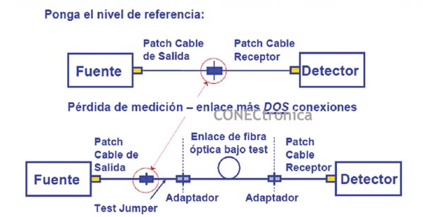
The first thing to do, as in the 1-wire method, is to establish the reference, but this time with a different scheme than before.
Observe how the coupler or adapter used to establish a reference remains during the measurement process, since the method involves the use of an additional measuring cable, with the same type of connector at each end as the one provided by the installation to be certified.
The 2-lead method is recommended when the 1-lead method cannot be used, as the accuracy is slightly worse than the 1-lead method but much better than the 3-lead method that will be discussed below.
3-Patch Cord Method
This method will be used when the connectors available on the measuring equipment are different from the connectors installed on the fiber optic trays.
The first thing to do, as in the 1-wire method, is to establish the reference, but this time with a different scheme than before.
![]()
![]()
In this case, and as the method name indicates, three patch cords will be required to complete the reference establishment scheme. The patch cords that connect to the measuring equipment must have a connector identical to the one on the measuring equipment at one end, and at the other end, they must have the same connector installed on the fiber optic trays. The third patch cord, used to connect the first two, will have the same type of connector at both ends, matching the connector used on the fiber optic trays of the installation being certified.
Again, once the reference has been made, the link to be measured must be inserted between the source and the receiver to perform the power loss measurement of said link.
With this third method, measurements can be made in permanent link or channel format (including also the fiber optic patch cords at both ends of the link), simply by removing or keeping, respectively, the adapters used to establish the reference.
The recommendation is not to use this method under any circumstances, given its lower precision or greater error compared to the other two methods discussed, except when channel format measurements are required, as it will be the only one that allows them.
However, neither of these two methods details the individual losses of the different components that make up the fiber optic cable channel/link; instead, they measure the total losses of that link/channel.
Using any of the three methods to establish a reference, the fiber optic links will then be measured or certified, as previously mentioned.
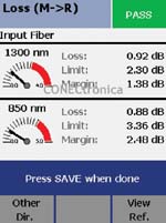
The measuring equipment should give us a PASS/FAIL result depending on whether the link attenuation exceeds the calculated limit and whether the measured length exceeds the maximum established by the standards. The result may be similar to that shown in the following figure, which displays the maximum attenuation values calculated for a multimode link in both working windows, and the attenuation values resulting from the measurement, as well as the link margin, which is the difference between these two values.
Level II Certification - OTDR
Level II certification, also known as reflectometry, is a complement to Level I certification, and never an alternative.
Typically, reflectometric measurements are performed to detect or resolve problems in fiber optic links, after a Level I certification has been carried out.
What happens if a Level I certification doesn't yield the expected results? A trial-and-error approach is possible, attempting to pinpoint the problem by cleaning or replacing components, but this is always a more arduous and time-consuming process than performing reflectometry.
Using an OTDR (Optical Time Domain Reflectometer), we can determine the total link length, the attenuation of each link component—connections, splices, fiber—and even identify if an excessive bend radius is causing the link's attenuation to exceed expectations.
The following figure shows a reflectometric graph, where you can see the total length of the link, the number of existing connections, identified by the peaks of the graph, and the number of splices or, failing that, excessive bends in the fiber, identified by steps.
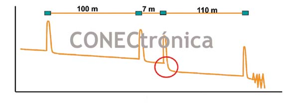
Most OTDRs also have the option to provide this data in numerical format, for better understanding by users who are not experts in the subject.
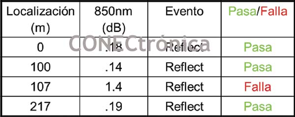
This table clearly shows the position of each element of the link, its attenuation, and whether or not it exceeds the attenuation set by regulations for that element and the total length of the link, so it is easy to deduce where the problem of excessive link attenuation can be found.
It is worth mentioning that there are two types of events. Reflective events are those caused by mechanical connectors or splices, and non-reflective events are those caused by fusion splices and excessive fiber bending.
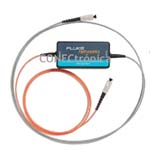
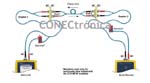
To perform reflectometry, it is necessary to have what are called "cast and receive coils." These coils, which are essentially sections of optical fiber of a length appropriate to the needs of the measuring equipment, are used to measure the attenuation of the first and last connectors of the link, respectively.
The need for this lies in the accuracy of the measuring equipment, also known as the "dead zone," which implies the requirement of a certain length of fiber between two events (connectors, splices, bends) so that they can be detected and measured by the OTDR.
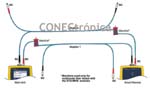
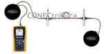
The following figure shows an example of an OTDR with launch and receive coils inserted within the link to be measured.
Inspection and Cleaning of Fiber Optic Connections
Finally, it should be noted that most problems related to fiber optic links in structured cabling installations are related to the cleanliness of the connections. Therefore, it is advisable to clean all connections before starting the certification process and follow an inspection and cleaning procedure for all connections to prevent any existing dirt from spreading and degrading link performance. The most dangerous dirt is dust, as it will block the passage of light and significantly increase link attenuation.
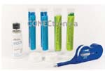
There are many cleaning accessories on the market, with dry cleaning accessories being highly recommended, as shown below.
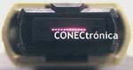
Cleaning MPO connectors commonly used in pre-terminated or pre-connectorized fiber systems is of vital importance.
This type of connector can align up to 12 fibers, allowing for up to 6 duplex fiber links. If one of these links is in production, but the remaining links suffer from excessive attenuation due to contamination and are therefore unsuitable for the intended applications, the connector cannot be cleaned until the active link can be disconnected, thus preventing the use of the remaining fibers.
Therefore, it is vitally important to clean these connectors before inserting them into the MPO modules or couplers.
An important point, and sometimes an alternative to Level II certification, which is commonly used to detect excessive attenuation problems in links, is the inspection of the connections.
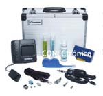 The following figure shows a complete inspection and cleaning kit. In addition to the cleaning accessories mentioned earlier, it includes a microscope with an LCD screen and a multi-magnification probe (typically between 200x and 500x) for inspecting the ferrule or surface of the connectors. This allows for real-time visualization of dirt at the point where light is transmitted between connectors.
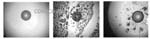
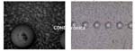
Examples of the dirt visible with these microscopes are shown below.
Author:
Article provided by CommScope Enterprise