 If working in the third transmission window (1550 nm), the low losses of these fibers, combined with the availability of erbium-doped fiber amplifiers (EDFAs), allow for covering long distances. However, despite their virtually unlimited bandwidth (several hundred THz), the presence of chromatic dispersion at 1550 nm limits the maximum capacity and range achievable in a given optical communication system.
Chromatic dispersion is a frequency-dependent delay introduced during propagation through the fiber, causing nonlinear distortion at the photodetector output. In other words, the frequency components that make up the optical signal spectrum travel at different speeds through the fiber and reach the photodetector at slightly different times. In digital transmissions, this effect manifests as a temporal broadening of the optical pulses, causing interference between symbols. Logically, as the optical pulses become narrower (higher modulation rates) or the fiber link longer (greater cumulative dispersion), the degradation becomes more pronounced. Therefore, there is a limit, usually expressed as the product of bandwidth and fiber length, measured in Gbit/s/km.
Research into new techniques and devices tolerant to chromatic dispersion has been actively underway for some time. Among the best-known devices are dispersion-compensating fibers, optical fiber diffraction gratings, and dispersion-shifted fibers. Regarding techniques, optical frequency modulation and spectral inversion stand out. We will now discuss each of these methods in more detail.
Dispersion-compensating fibers
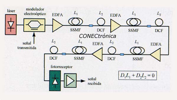
Dispersion-compensating fibers (DCFs) are characterized by having a high chromatic dispersion parameter with the opposite sign to that of conventional fibers operating in the third window. Thus, by placing a certain length of DCF after the optical fiber link that constitutes the communication system, it is possible to compensate for the chromatic dispersion accumulated during the first path. If we denote D1 and L1 as the dispersion and length of the fiber link, and D2 and L2 as the dispersion and length of the DCF, respectively, then the condition for dispersion compensation can be written as: D1L1 + D2L2 = 0. Assuming we have an optical link formed by 100 km of standard fiber (D = 17 ps/km·nm), the accumulated dispersion during propagation through it would be 1700 mps/nm. Therefore, based on a DCF with a dispersion parameter of approximately -100 ps/km·nm, about 17 km of DCF would be needed to achieve compensation. Figure 1 schematically represents a long-distance optical link that uses DCFs to compensate for chromatic dispersion. The signal to be transmitted is fed into the system by an electro-optical modulator located at the output of the laser optical source and is received by a photodetector along with a broadband electronic amplifier. To equalize the dispersion introduced along the link, it is divided into sections composed of a segment of SSMF, a certain length of DCF, and finally, an EDFA to recover the signal power. Although the figure depicts the technique based on "post-compensation," "pre-compensation" could also be performed simply by swapping the positions of the SSMF and DCF segments.
 Despite the above, DCFs suffer from several problems. First, 1 km of DCF only compensates for about 10.12 km of standard fiber (recent advances have made it possible to produce fibers with dispersion exceeding -200 ps/km.nm). Second, their losses are relatively high at 1550 nm (around 0.5 dB/km). And third, due to their small mode diameter, the optical intensity inside the fiber is higher for the same optical power, which accentuates nonlinear effects. Currently, work is underway to improve the performance of DCFs. Some results already obtained are based on a bimode fiber structure, achieving dispersion parameters as high as -770 ps/km.nm with identical losses to standard fiber.
Dispersion-shifted fibers
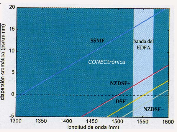
Dispersion-shifted fibers (DSFs) are not strictly a dispersion compensation device, but rather a type of fiber used as a replacement for conventional fiber due to their non-dispersive properties. Standard fiber exhibits increasing dispersion with increasing wavelength, reaching zero around 1310 nm (second window). Since working in the third window is desirable due to the fiber's low losses, the goal is to develop a new type of fiber that exhibits zero dispersion around 1550 nm. This is how DSFs came about, their name derived from the manufacturing process that modifies the core radius or the difference in refractive index between the core and cladding to shift the characteristic dispersion curve of standard fibers towards longer wavelengths.
 However, the manufacturing process of these fibers itself results in a decrease in the effective core area (50 mm² compared to 70-80 mm² for standard fibers), which intensifies the device's nonlinearities. Since nonlinear phenomena are favored in zero-dispersion regions, this means that the main limitation in these links now becomes nonlinearities over chromatic dispersion. The most immediate solution is to construct DSFs with dispersion parameters small enough to avoid the dispersion limitation and, at the same time, reduce the influence of nonlinearities. This type of fiber is commonly called NZDSF (nearly zero DSF), and there are two types depending on the sign of the dispersion parameter. Figure 2 summarizes the dispersion characteristics as a function of wavelength for the different types of optical fiber discussed: SSMF, DCF, DSF, and NZDSF.
Diffraction gratings on optical fiber
Without a doubt, the key devices used to compensate for chromatic dispersion are chirped fiber gratings (CFGs). Like DCFs, they are dispersive devices but with notably different characteristics. Their main advantages are low insertion loss, compact size (on the order of centimeters in length) allowing for integration, and relatively easy mass production. Their operation is based on introducing a wavelength-dependent delay to the optical signals injected into the device, thus compensating for the variable delay introduced by the fiber optic link. The CFG typically has a single input/output port and operates in reflection mode. Since both the received and equalized signals are present at this port, a circulator is needed to separate them, as shown in the block diagram in Figure 3. This is the standard configuration, although CFG-based filters that operate in transmission mode instead of reflection mode also exist.
The variable delay is achieved through chirp modulation of the fiber's refractive index frequency. This causes optical signals traveling through the fiber to reflect at different points depending on their wavelength, thus covering varying distances. Figure 4 illustrates this phenomenon, as well as the typical reflectivity and group delay responses of one of these devices. Note that the CFG is characterized by a specific operating bandwidth that depends primarily on the device's length. Unlike the DCF, this is the CFG's main limitation. Currently, research is underway to develop wideband CFGs for use in DWDM (Dense Wavelength Division Multiplexing) systems.
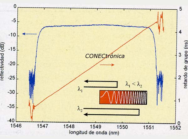 The CFG manufacturing method involves placing a phase mask between an ultraviolet light beam and the optical fiber. The incident beam is diffracted by corrugations in the phase mask and strikes the photosensitive fiber core, modifying the refractive index and modulating it. Since this manufacturing process is not perfect, some random ripple appears in the reflectivity and group delay responses, as shown in Figure 4. In the case of group delay, this ripple leads to higher-order dispersive phenomena that ultimately degrade the system's quality, especially in analog multichannel systems.
Optical frequency modulation
An alternative approach to what is known as dispersion-tolerant transmission is optical frequency modulation. In this case, the FSK modulation format is typically used to inject the data signal to be transmitted onto the optical carrier generated by the laser. The modulation consists of a shift Δl of the carrier wavelength depending on the bit (“0” or “1”). During propagation through the fiber, the two wavelengths travel at slightly different speeds. The delay between the bits “0” and “1” can be determined from the separation Δl and is given by ΔT = ΔLΔl, where L is the length of the fiber link. Then, by taking a certain separation such that ΔT = 1/B, where B is the modulation rate, it can be shown that the pure FSK signal is converted into an amplitude-modulated signal at the receiver. Finally, using an integrator along with a decision circuit, it is possible to recover the transmitted signal. Using this technique, the transmission of 10 Gbit/s signals over 253 km of SSMF and 20 Gbit/s signals over 53 km of fiber has been demonstrated, confirming that the transmission distance can be increased considerably.
Spectral inversion technique
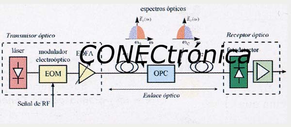
The spectral inversion technique, also known as OPC (optical phase conjugation), has proven to be an efficient method for compensating for the degradation caused by chromatic dispersion in long-distance optical communication links. This technique is based on placing a conjugator device in the middle of the optical link, which inverts the phase of the optical signal. Assuming that both fiber segments before and after the conjugator have identical characteristics and length, propagation through the second segment compensates for the dispersion accumulated at the output of the first. The name spectral inversion comes from the conjugation process itself, as it is equivalent to rotating the modulation spectrum. In this way, the dispersion accumulated during the second fiber segment is now subtracted from that introduced during the first part of the link. Figure 5 schematically represents the block diagram of a system that uses the OPC technique. Although L1=L2=L/2 is generally used, it is also possible to use different lengths if other link parameters are adjusted, such as optical power or the dispersion and non-linearity characteristics of the fibers.
 One of the main advantages of OPC is that it also compensates for the degradations introduced by the combined effect of chromatic dispersion and nonlinear effects. Furthermore, unlike techniques based on the use of DCFs or CFGs, the equalization results obtained with OPC exhibit reduced sensitivity to variations in parameters along fiber lengths within the system, thus eliminating the need for overly meticulous link design. In this way, the OPC device can be located in a common area (control station) and shared among a number of optical nodes interconnected by fiber links of slightly different lengths, resulting in significant cost savings. Using this technique, transmission of 40 Gbit/s signals over 400 km of SSMF has been demonstrated at the laboratory level, confirming its effectiveness in compensating for chromatic dispersion. Currently, work is underway to apply this technique to next-generation DWDM optical networks.
Construction of the optical conjugator
Since the OPC device is the key element, we will analyze it in more detail. The construction of the optical conjugator is based on nonlinear processes that occur in certain optical devices and lead to the phase inversion of the optical signal. The most commonly used method employs four-wave mixing (FWM) in a nonlinear medium. There are two main possibilities for this: the first based on a semiconductor optical amplifier (SOA) and the second on a DSF. In either case, a pumping laser is necessary to induce noticeable nonlinear effects. The input optical signal is mixed with the pumping inside the SOA or DSF and appears conjugated at its output, albeit at a different wavelength. Subsequently, this conjugated signal is selected by means of an optical filter and finally amplified if necessary. The block diagram of this device is shown in Figure 6. The optical spectrum at the conjugator's output, where the newly generated signal can be seen, is also shown in the same figure.
The relatively low efficiency of the conjugation process in optical fibers deserves special mention. Typically, the conversion efficiency is below 1%, necessitating further amplification of the conjugated signal. However, the FWM phenomenon is not inherently an inefficient process and can, in principle, provide gain. In fact, analysis of the equations modeling FWM shows that efficiency increases considerably by increasing the pump power while decreasing the signal power. It can even exceed 100% by optimizing power levels and the difference between the pump and signal wavelengths, although high power levels are generally avoided due to Brillouin scarting, which occurs around 10 mW. Brillouin scattering is a nonlinear process in optical fibers whereby the injected optical power is reflected at the fiber entrance above a certain value that depends directly on the fiber length. This limits the maximum applicable pumping power and also results in an increase in noise intensity at the outlet.
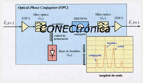 Regarding SOA-based conjugators, conversion efficiency is generally higher than that of FWM in DSFs due to amplification. The conjugate signal can be generated using a device 1 mm in length or even shorter. However, this advantage is reduced by the high coupling losses that occur when the signal is reinjected into the fiber. By appropriately selecting the separation between the signal and the pump, conversion efficiencies above 100% can be achieved, meaning a net gain on the conjugate signal. These characteristics make this technique very attractive in dispersion compensation systems. Nevertheless, the conversion efficiency and signal-to-noise ratio of FWM in SOAs are highly dependent on this separation between the signal and pump waves. Therefore, various techniques have been proposed to try to equalize this response in the operating band.
For the FWM process to operate with maximum efficiency, it is essential that both waves have the same polarization state at the input of the nonlinear medium. This is achieved by means of a polarization controller (Figure 6) on the pump wave when the polarization of the signal wave is known and stable. However, the polarization of the electric field during propagation through optical fibers varies randomly, making it impossible to know its state at the OPC input in a real dispersion compensation system beforehand. These random variations significantly affect the efficiency of the FWM process, rendering the spectral inversion technique unsuitable for real-world applications. Fortunately, this topic has been actively researched, and FWM configurations insensitive to the polarization of the input signal have been found. These include several experiments using polarization diversity techniques or two orthogonally polarized pump waves. New techniques have recently been proposed based on Mach-Zehnder and SoAs interferometer structures, Sagnac interferometers, or even DFB lasers built on fibers that achieve a polarization dependence as small as 0.5 dB.
In addition to the polarization problem, the FWM conjugation process introduces another undesirable effect: optical carrier shift. This is a factor to consider in OPC dispersion compensation systems, as the propagation properties along the second fiber path will be different, and the available optical transmission bandwidth will be halved. To avoid this effect, various configurations based on the use of two orthogonal pump waves have been proposed. Finally, the influence of other effects, such as distortion due to residual phase amplitude modulation of the conjugate signal or phase noise of the pump signal, also affects the performance of the OPC technique and must be taken into account in the conjugator design.
Author: Francisco Ramos Pascual. Telecommunications Engineer. Professor of Radiocommunications at the Polytechnic University of Valencia